TransporTable – Design Collaboration Space

Our table with trapezoidal shape steel frame with folding tabletops is designed to replace the existing collaborative project tables in Bonderson 104. To promote minimum storage foot print, our table stacks together in a similar manner to the common shopping carts.

Our Team

Head shot of Jung

Jung Kim

Team manager

My name is Jung Sub Kim (I go by Jung with a J- not Y- pronunciation). I am currently staying at Fullerton, CA. I am pursuing to become a fire protection engineer after I receive my bachelor’s degree. Besides my personal goal, I would like to contribute to our project to extend the mechanical design skillsets I received to an actual practical application.

Headshot of David Yang

David Yang

Documentation / Manufacturing

Hey, my name is David Yang! I’m from Irvine, CA and my concentration is General. I’m most interested in vehicle dynamics and  manufacturing. Apart from schoolwork, I love to be outside – hiking, trail running, and rock climbing are all in my repertoire. I also love working on cars!

Team Member

attache / manufacturing

Hi! I’m Ellie Kitabjian and I’m a fourth year Mechanical Engineering student from San Diego, California. I am interested in Space Systems Engineering and satellite design. When I’m not working I like to play soccer and go for runs.

Team Member

Treasurer

Hello, my name is Christopher Macias and I’m from Fresno, CA. In general, my interest in mechanical engineering is in being able to design something that has a purpose. It’s always satisfying to see your work coming together into a functional system.

Acknowledgements

Special Thanks to our sponsor/coach, Peter Schuster and Sarah Harding, and also to CPConnect Funding. 

Problem Statement

Existing collaborative tables lack the key combination of transportability, compact storage, surface quality, and durability for group projects. College students need an ergonomic, multifunctional table unit capable of supporting all levels of interactive work, from one-on-one tutoring to large group prototyping sessions to maximize productive time in a busy day.

Design Constraints

  1. Compact Storage – Four tables shall fit in a footprint no larger than 1.5x its stacking direction.
  2. Table Height – Minimum of 30 in.
  3. Deployment Time – Maximum of 30 seconds.
  4. Fold Time – Maximum of 45 seconds.
  5. Cost – Maximum of $350.
  6. Tipping load – Withstand 125 lb. at edge.
  7. Concentrated Load – Withstand 200 lb. 
  8. Drop Test – Endure drop from 2.4 in.
  9. Leg Strength – Withstand 100 lb.

Existing Design

Existing Bonderson Single-Axis Folding Table
Existing table Stacked

The major problem of the existing single-axis folding table is the shakiness and wobble caused from the hinge system. The stacking efficiency (Ratio of Single table foot print to the footprint of two stacked tables) is 76%.

Initial Sketch

Sketch of Nesting base and folding tabletop
Ideation of Trapezoidal frame geometry

A trapezoidal base promotes compact nesting, and the center-split table allows for fast deployment and folding. Our initial concern was the dimensions of the trapezoidal frame since increasing its size limits the stacking efficiency.

Design Analysis

Stacking efficiency

Base Angle Study

Finding the Optimal Base Angle for Maximum Stacking Efficiency

The figure on the left demonstrates the base angle dimension shown with black lines on the mock up trapezoidal table frame. The right side figure shows the relationship of base angle to the stacking efficiency (Ratio of Single table foot print to the footprint of two stacked tables) derived from CAD model study. The greater the base angle, the greater the stacking efficiency. Our final table design has a base angle of 36°, and stacking efficiency of 78%

load / tipping analysis

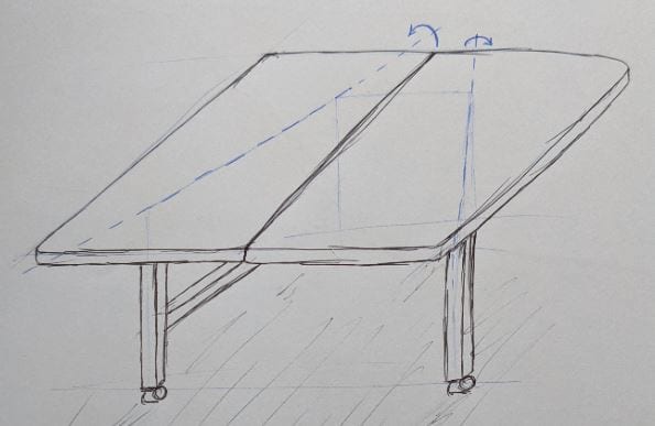
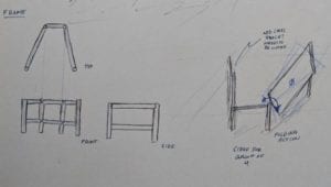
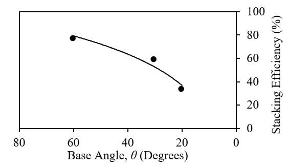
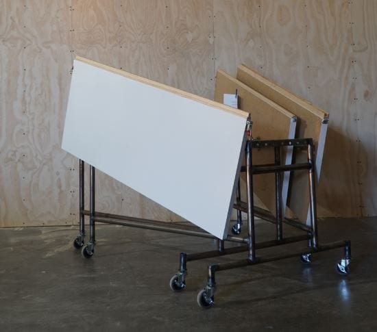
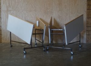
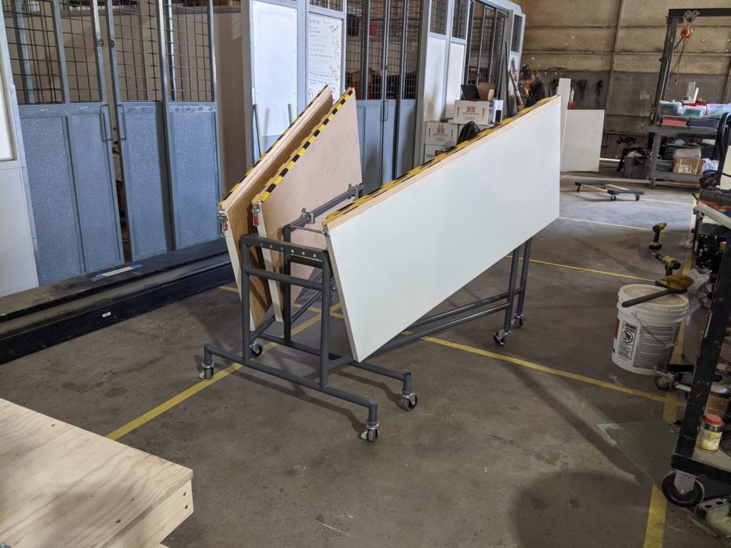
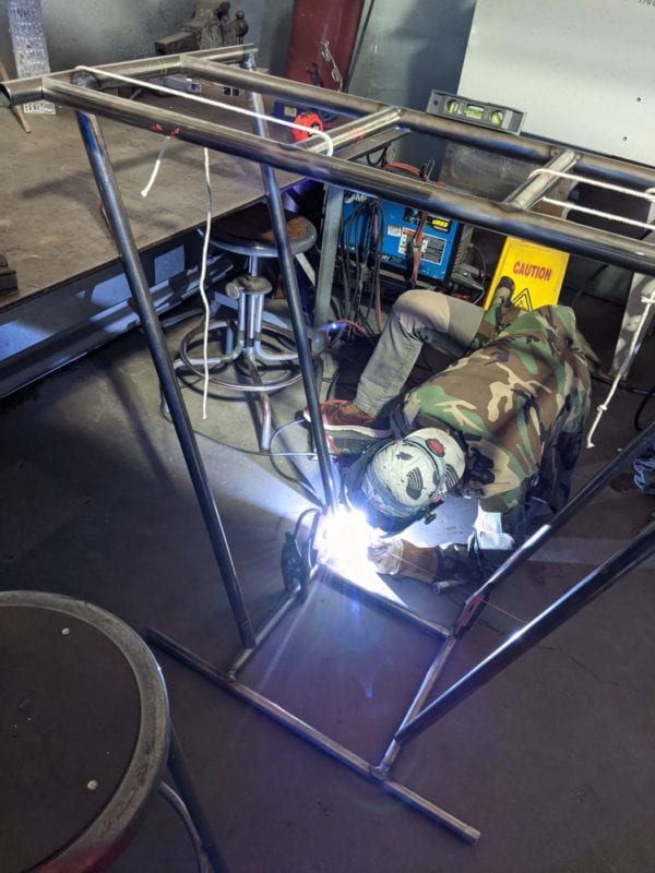
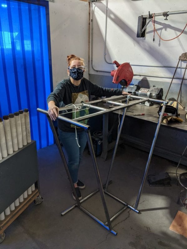
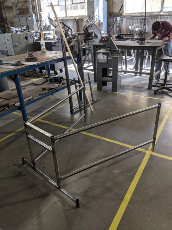
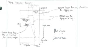
Trapezoid frame dimensions was optimized using an excel spreadsheet calculations. Above figure shows the diagram that was used for the calculation. Major constraint of the frame was to resist tipping, and optimization process was a compromise among the Stacking efficiency, Overall weight (Pipe Thickness), and the Tipping resistance.  

UHMWPE Bushing Wear analysis

We conducted a wear test of UHMWPE bushing by spinning a steel pipe along the assembled bushing with a lathe, which helped us to find a set of optimal bushing dimensions and tolerances.

This project is sponsored by Dr. Peter Schuster of Cal Poly San Luis Obispo Mechanical Engineering department and also by CPConnect.

Final Design

Specifications
Weight -56 lbs     Dimensions -55” X 48” X 31”     Price – $348

Custom Components

1.25″ Steel Pipe welded Frame

UHWMPE (Ultra high molecular weight polyethylene) Bushing

Steel Plate Bushing Carrier

Hardwood Tongue and Groove

Stock Components

2X IKEA LAGKAPTEN (55x24x1.4)
4X Caster Wheels
1X Compression Latch
Anchor Hardware and screws
Bushing Installed

Two (2) Bushing subsystems join one (1) tabletop to the frame. The UHWMPE bushing smoothly slides and rotates along the frame, but provides enough friction so that the tabletop does not drop down when being folded.  

Exploded Bushing View

A bushing subsystem includes two pieces of matching UHMWPE milled bushings, a waterjet cut and folded steel plate bushing carrier, and six (6) screws – three on each side . The bushing carrier holds the bushing in place when in movement.

Bump Stop (Orange)

The bump stop subassembly is fixed to the frame to prevent over-rotation of the tabletops. It is made of steel plates, folded, and notched to be welded on the frame.

Compression Latch

To hold the joining assembly in place, we installed a compression latch onto the sides of the table. This will aid the joining slots in bearing the loads.

Warning Label across Tongue and Groove

The tongue and groove feature created a pinch hazard when the table is being deployed. To prevent this hazard, black/yellow warning tape was applied across the feature.

EZ Anchor in Tabletop

Drywall Anchors are installed on the surfaces of the tabletop to attach the hinge brackets and compression latches. Anchors allow multiple installs/reinstalls of the screws.

Outrigger and Caster Wheel

According to our tipping analysis, the trapezoid shape frame could not handle the design tipping load. To address this deficiency, outriggers were welded on the frame. Four (4) caster wheels were installed for ease of mobility.

Tongue and Groove model

The horizontal extension (tongue) is shown on the left, and the horizontal slot (groove) is shown on the right. This feature guides the table deployment, as well as bears the vertical load.

Concept Design

Concept Hinge Design

The initial Concept design of the hinge design was carried over to the final design. The initial design had circular PVC pipes which were replaced with UHMWPE four (4) point contact rectangular bushings.

Concept Trapezoid Table

the concept CAD design of the table did include the finer details of the frame and table as a whole, but focused on the geometry of the frame as well as the ideations of the hinge.

Concept Prototype

A concept prototype (1:1 scale) was made out of two (2) 12″x48″ plywood, ABS pipe frame, and PVC collar hinges.

Concept Prototype Usability

A preliminary usability test was performed on the concept prototype to experience the usage of the trapezoid-frame table and identify issues that needed correction.

Design Verification

Usability testing highlights

Deploy and Stow Test- Seven (7) participants without experience with the table were timed deploying and folding the table. The average deploy time was 34 seconds (Max 30 seconds in design criteria) and the average folding time was 33 seconds (Max 45 seconds in design criteria).

Stacking Efficiency Test- Measured the physical dimension of two tables stacked together to confirm the design stacking efficiency. Measurement showed  approximately .5% increase in the actual storage foot print compare to the anticipated storage foot print.

Long Term Usage Test- From our internal usage test, we evaluated that 1) the bushing carrier heavily affected how the hinge sliding feels 2) the bump stop assembly was updated from a design with a potential pinch hazard to a pinch free design 3) we needed to install anchors on the tabletop edge for compression latch mating 4) the trapezoidal frame shape did not interfere user’s legs and 5) the tongue/groove lacked the anticipated vertical load support.

durability testing highlight

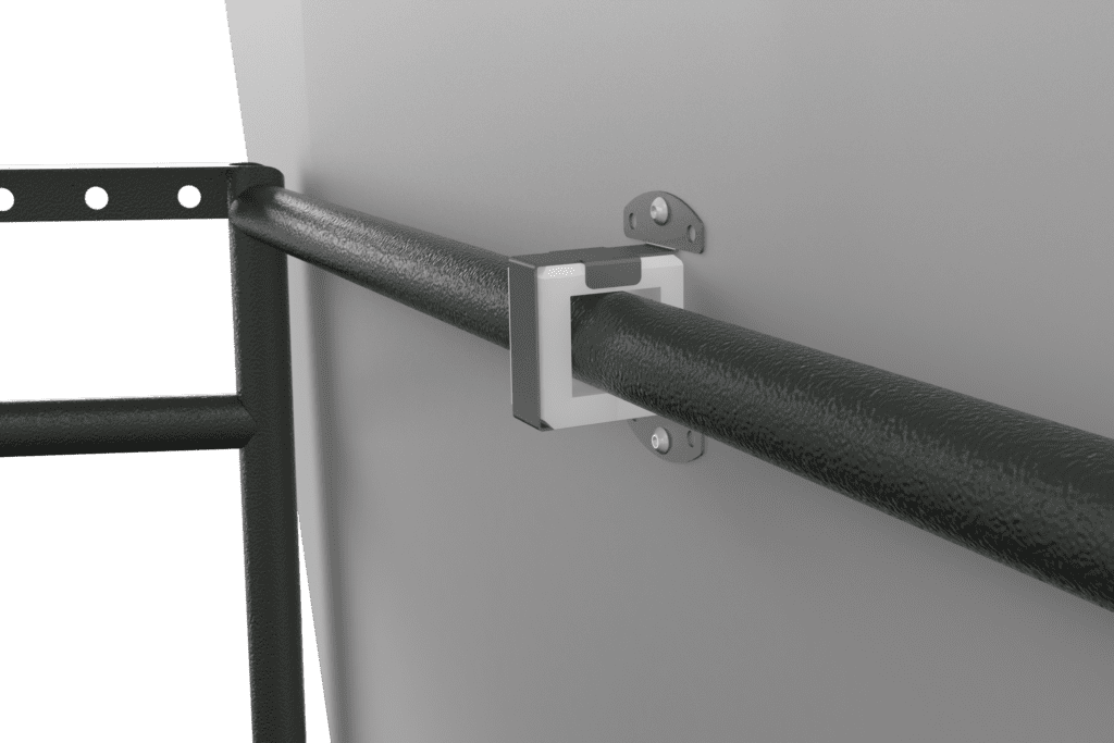
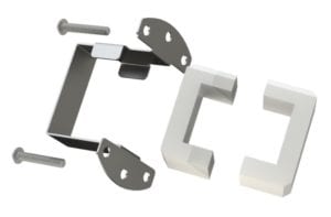
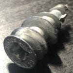
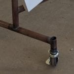
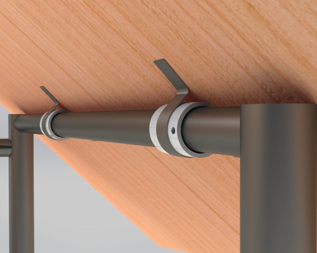
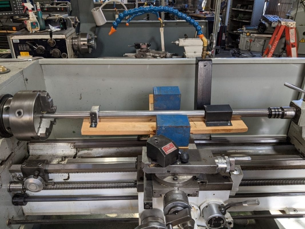
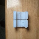
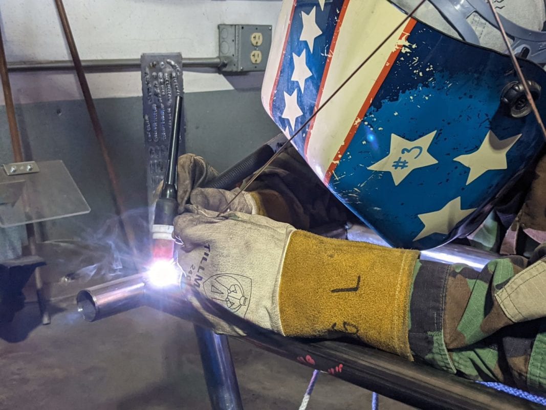
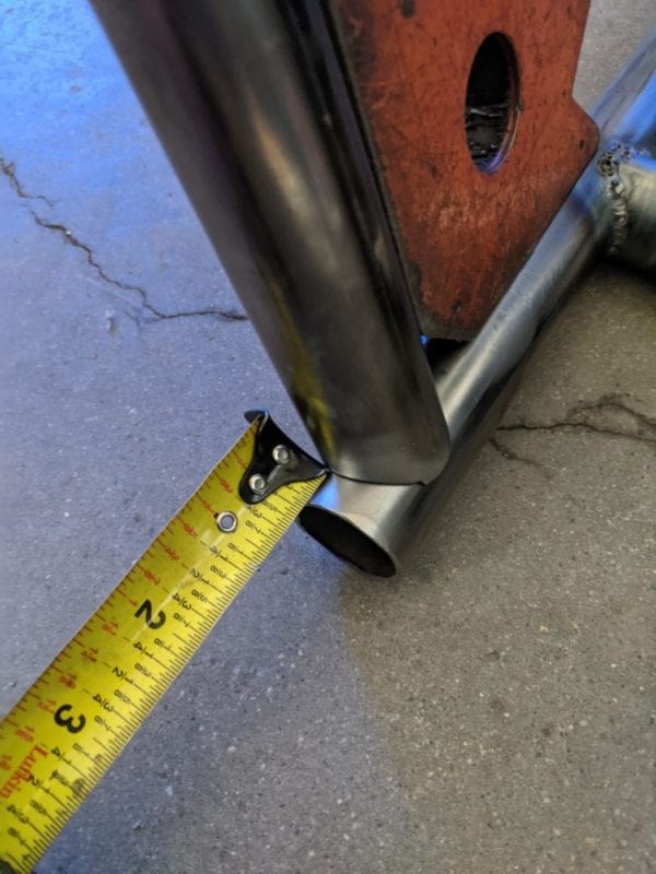
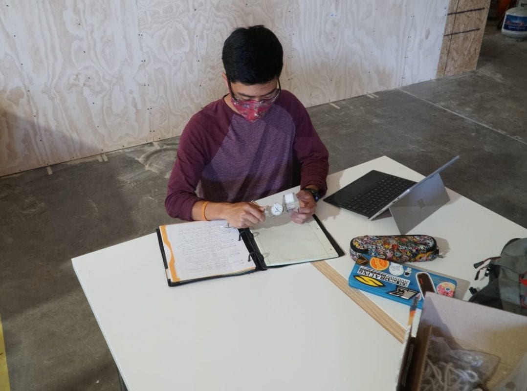
Statistical Bushing Carrier Manufacturing Test- We  noticed from the long term usage test that the bushing dimensions (A and B) determined the fitting of the hinge to the frame pipe. By manufacturing multiple bushing carriers and testing out the fittings, we developed proper tolerances for the critical bushing carrier dimensions which will help benefit possible mass-manufacturing.

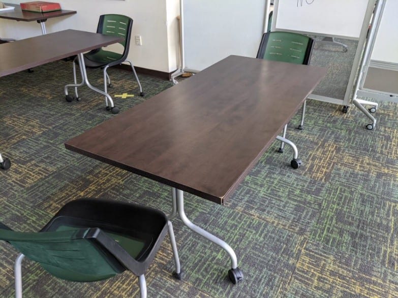
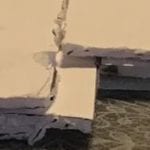
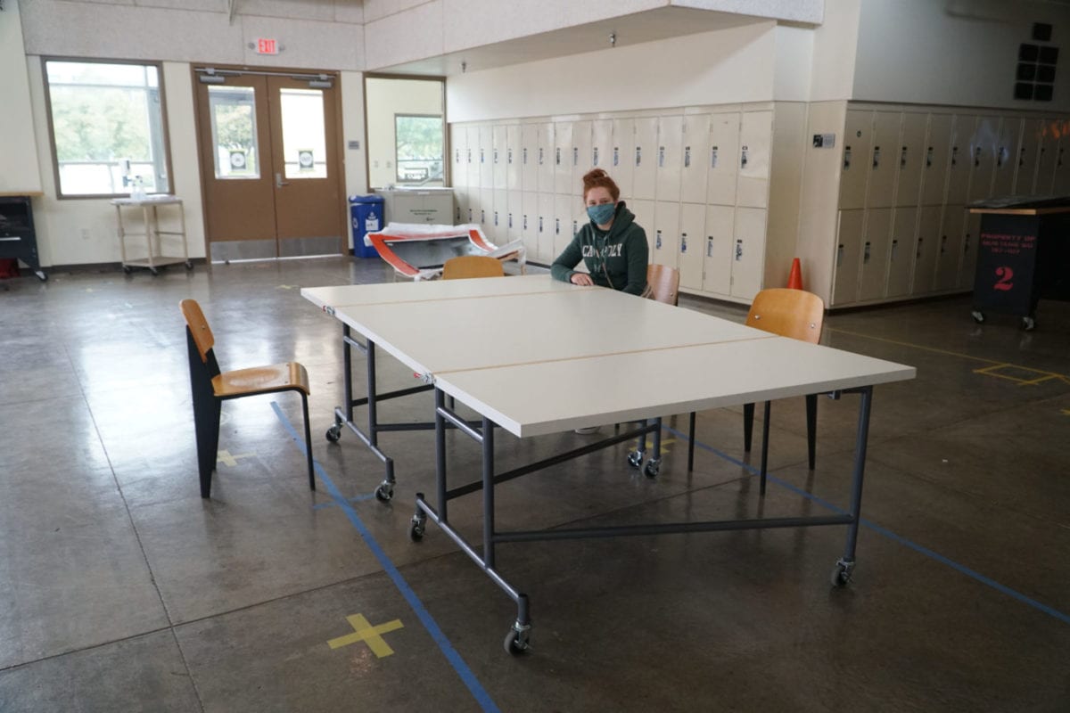
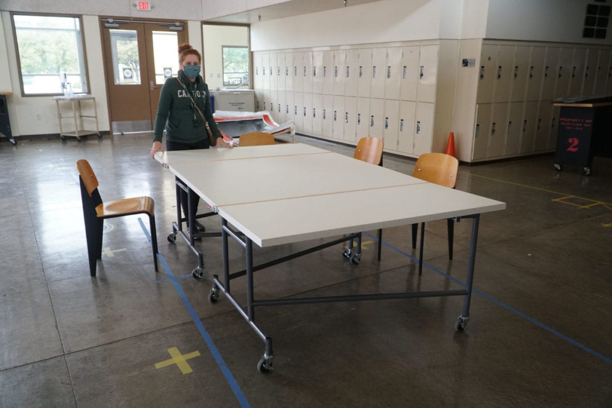
BIFMA (Business and Institutional Furniture Manufacturers Association) Tests- BIFMA offers design constraints for office tables, which include 1) 125 lb. maximum tipping load, 2) 200 lb. maximum concentrated Load, 3) 2.4 in height drop test, and  4) 100 lbs. minimum leg strength. Our verification prototype passed all the BIFMA required tests except the 200 lb. concentrated load (102 lb. actual), presumably due to the current tongue/groove feature design.

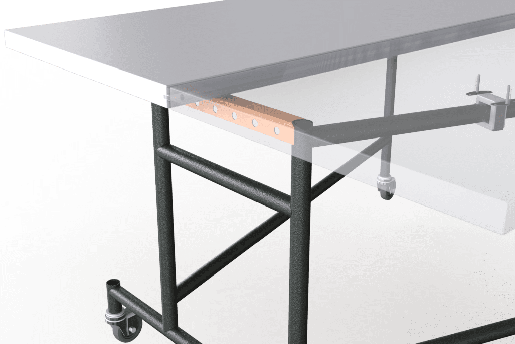
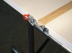
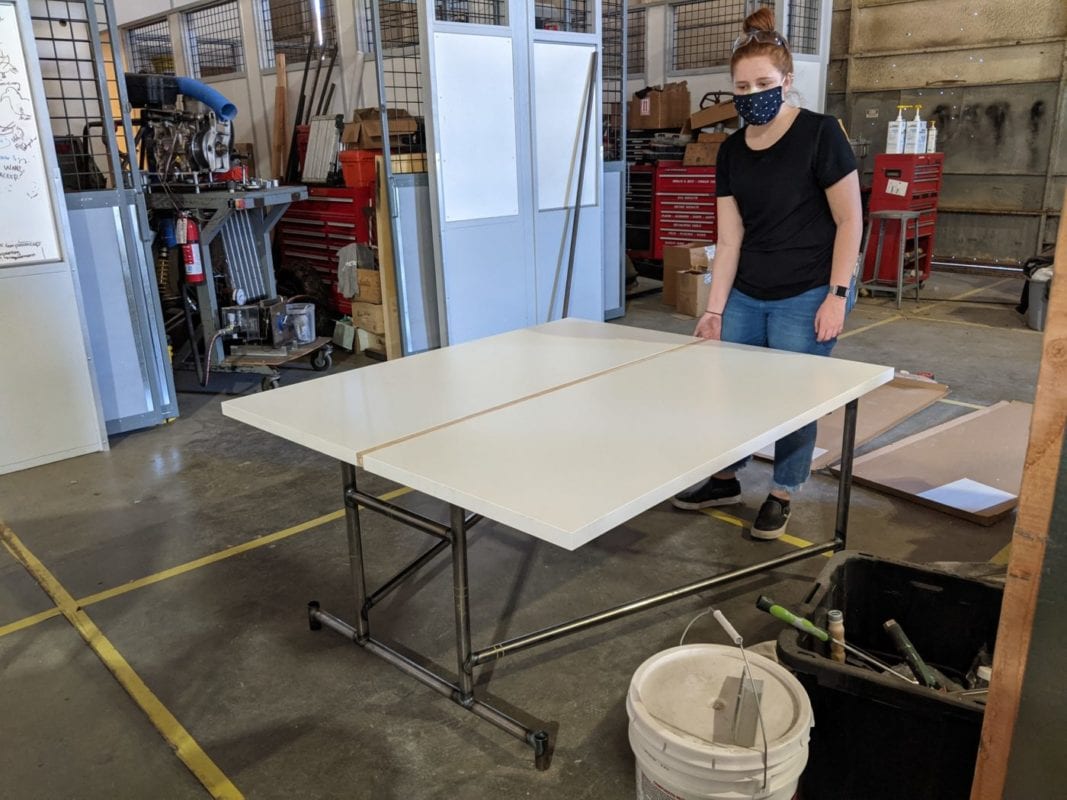
Hardware Compatibility Test- We tested multiple types of hardware on our special IKEA table top (Particle board shell with hex paper filling) to ease the subcomponent assembly process and also for future repair process. The tests included a weight drop test, creep test, and destructive test.
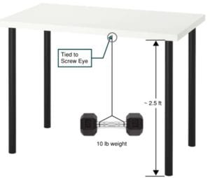
Recommendation

We recommend the further improvement of the tongue and groove feature which joins the tabletops together when in the deployed configuration. The design of that feature was the major reason we did not achieve the goal of supporting a concentrated load of 200 lbs. Other than the issue with the concentrated load, our fully built verification prototype was able to meet all the engineering specification we anticipated from the design as well as other criteria we had not previously defined, such as wobble-free hinges and repair-friendly tabletops equipped with anchor hardware.

Our Project's Videos

Have a Question About this Senior Project?

Send an email to pschuste@calpoly.edu to be connected with the project team. Please include the title of the senior project you’re inquiring about in the subject line.

Interested in Sponsoring a Mechanical Engineering Senior Project?

Visit our Sponsorship Page to learn more!

Check Out More Projects!

Visit our ME Senior Projects Page to view the latest Mechanical Engineering senior projects from the class of 2021!

Share

Share on facebook
Share on twitter
Share on linkedin