Our Team

Logan Christensen
ELECTRONICS LEAD
Logan is a mechanical engineering student from Sacramento, CA. Logan took the load on selecting the powerplant and electronics of the UAV. After graduation, he will move to Seattle, WA to work for Siemens doing technical sales.

Richard Barakat
STRUCTURES LEAD
Richard is a mechanical engineering student from Monterey, CA. Richard designed the fuselage and structural systems of the UAV. After graduation, he will continue his studies as mechanical engineering graduate student.

Brandon Halebsky
PAYLOAD LEAD
Brandon is a mechanical engineering student concentrating in mechatronics. Brandon designed the payload storage and release mechanism and took the lead on ground operations. After graduation, Brandon will pursue a career designing robots for space systems.

Justin Slavick
AERODYNAMICS LEAD
Justin is a mechanical engineering student from San Diego, CA. Justin took the lead on aircraft propulsions by sizing and shaping the rotors, wings, and propeller. After, graduation, Justin will pursue an advanced engineering degree with a focus on aircraft systems.
Acknowledgements
We would like to thank our Senior Project Advisor, Peter Schuster, for his guidance and through all stages of the design process and dedication to supporting our team’s success. We would also like to thank Professor Hiremath for assisting our wind tunnel testing.
Project Video
Our Project's Digital Poster
Problem Statement
Develop an unmanned vertical lift concept that can deliver, at high speed, up to 50 kg payloads to end-user customer sites up to 50 km radius, and to logistics centers up to 200 km away. Size the vehicle such that it can make a difference within a future pandemic or natural disaster. Utilize only current year (2020) technologies in order to support an initial entry into service in 2025.
Design Constraints
Takeoff and land vertically
Vehicle size:
15′ x 15′ (objective)
20′ by 20′ (threshold)
Store 50 kg payload at two sizes:
70 cm x 70 cm x 70 cm and
140 cm x 50 cm x 50 cm
Fly 200 km in less than 75 minutes
Fly 50 km in less than 28 minutes
System shall be unmanned and autonomous
Design Process
Aircraft Configuration
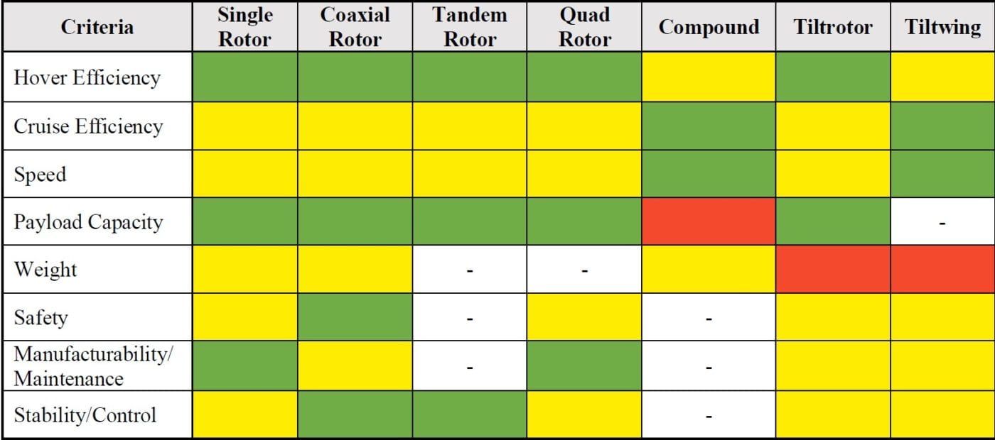
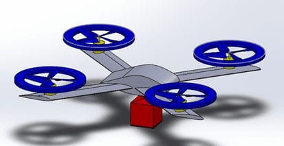
We evaluated and compared several commonly used aircraft configurations. We selected a quad rotor configuration due to its excellent performance in hover and ability to be configured with other aerodynamic components such as wings and a propeller.
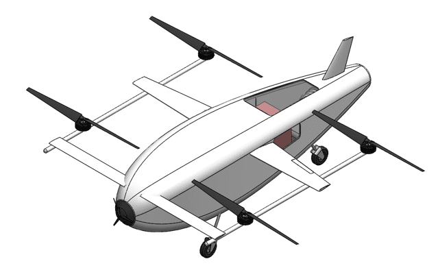
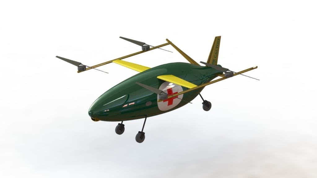
Our second UAV design introduced a front propeller to eliminate the requirement for the UAV to pitch down. The payload was moved inside the fuselage to reduce drag. The main issues with this design were the fuselage shape which was not optimized to minimize drag and the placement of the propeller at the front which increased drag.
powerplant selection
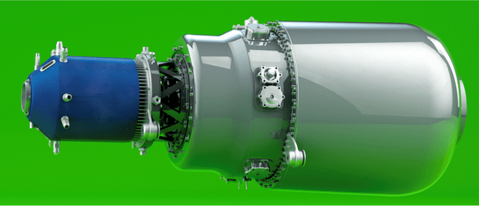
We selected a 90 kW turbogenerator which has a high power-to-weight-ratio and runs on fuel which has a much greater energy density than batteries. A turbogenerator allowed us to supply electric power to the motors using lightweight power conversion and energy storage.
payload release mechanism
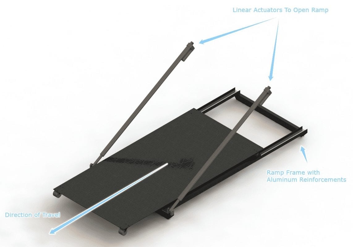
The competition required a design that could accurately and autonomously release a payload and while not damaging the payload. We selected this final design because it can gently release the payload to a precise location using the various limit switches and proximity sensors to know exactly where the payload is at all times in the unloading process.
fuselage shape & strUCTURE
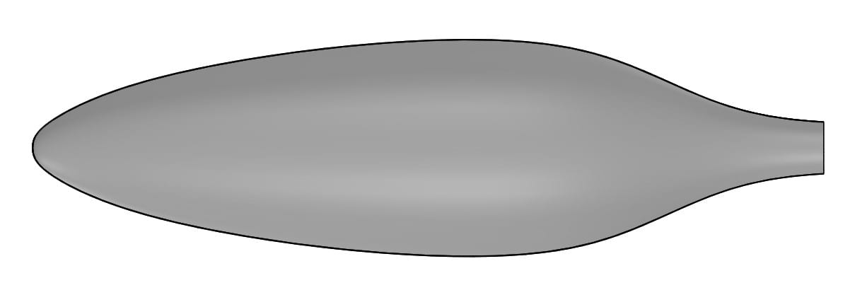
We selected this axisymmetric fuselage shape because a previous study has found that this body profile promotes laminar flow along the surface at aerodynamic conditions near our operating point and thus minimizes drag.
Semi-monocoque: We selected a semi-monocque structure for the fuselage as it is the lightest structural option capable of withstanding the expected loads and being manufactured into our desired fuselage shape.

38th Annual Student Design Competition hosted by the Vertical Flight Society and sponsored by the Boeing Company
Analysis
Rotor Blade Selection

The propeller and rotor blades were sized to reduce the power and weight as much as possible. In general, large blade radii are more efficient than smaller ones for a given rotor RPM and aircraft weight.
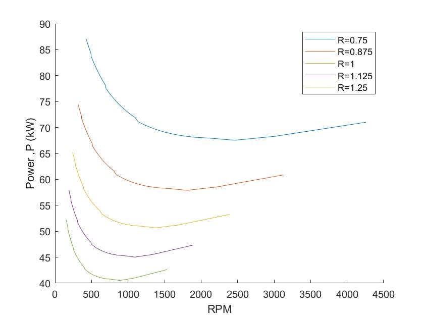
To select the radius of each blade, we analyzed the power over a large range of blade speeds for each size using Blade Element Momentum Theory.
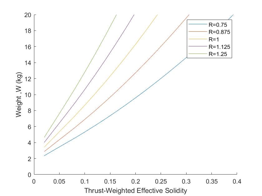
The best RPM is determined by the thickness, or solidity, of the blades, so a comparison between solidity and the combined fuel and rotor weight was used to supplement the RPM and radius selection.
Wing and tail sizing
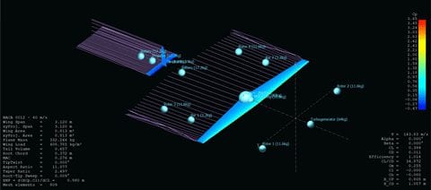
The size and shape of the wings directly affects the ratio between lift and drag while in flight. XFLR5 aircraft analysis software and Prantl’s Lifting Line Theory was used to select the wing size that would allow the aircraft to travel the fastest with the least amount of drag force. From there, the tails were statistically sized with respect to the main wing geometry to ensure static aircraft stability while flying.
Design Verification
prototypes
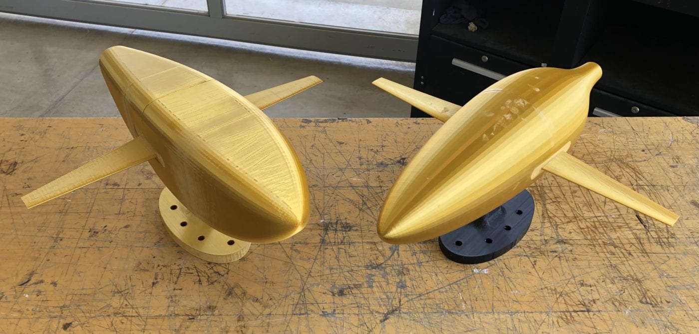
We designed and 3D-printed simplified models of our UAV with two different fuselage shapes using a scaling factor of 1:8 for both. The aircraft models were comprised of five major components: the front half of the fuselage, rear half of the fuselage, right wings, left wing, and stand.
Testing
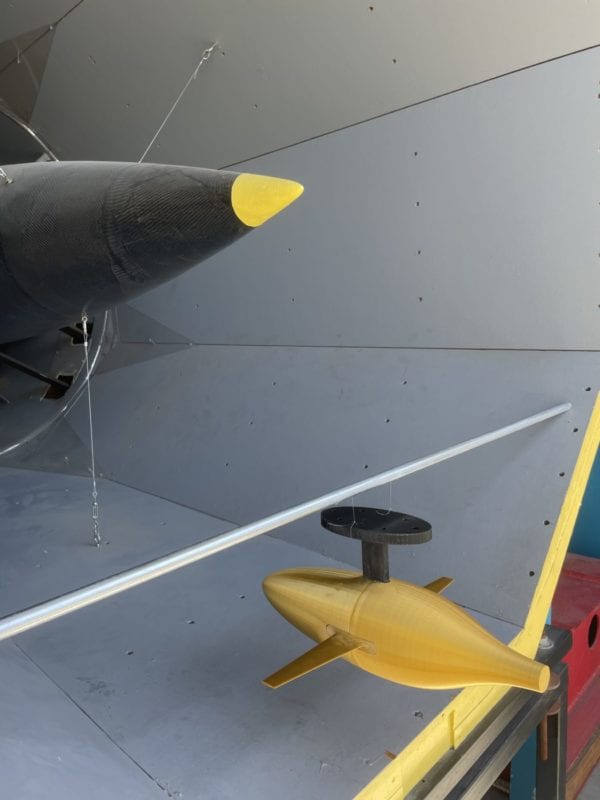
Wind Tunnel Test – We suspended each model behind the outlet of the Cal Poly Aerospace Wind tunnel and subjected them to wind speeds of 15 mph. We measured the amplitude of oscillation about the fixed pivot for both models. We observed the new axisymmetric fuselage (shown in figure above) to be more stable and oscillate less than the original fuselage indicating a lower drag force and better fuselage design.
Final Design
Specifications
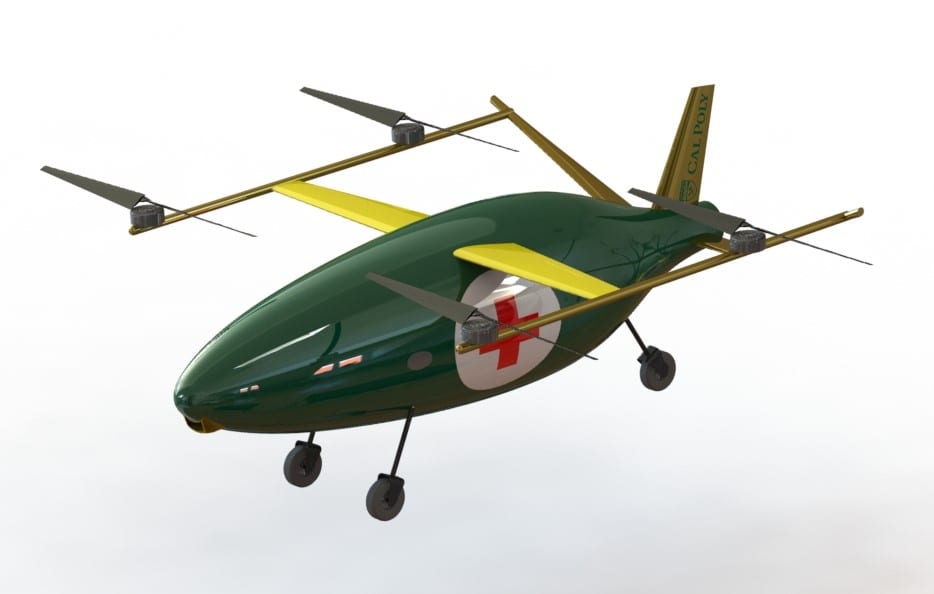
Weight: 349 kg (770 lbs)
Dimensions: 5.02 m x 4.28 m x 1.88 m (16.5′ x 14.0′ x 6.2′)
Cruise Speed: 90 m/s (200 mph)
Power Generation: 90 kW
Fuel Consumption: 17 liters (200 km mission)
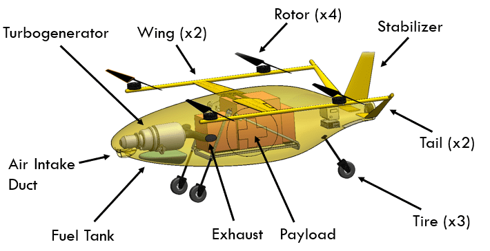
Custom Components
• Fuselage
• Wings
• Rotors
• Propeller
• Tail and Stabilizer
• Intake Duct and Exhaust
Stock Components
• TG-R90 Turbogenerator
• EMRAX 208 Motor
• EMRAX 228 Motor
• 1000mm Stroke Linear Actuators
• Badland 2000 Electric Winch
• AP 10.1 onboard control system
• PGCS ground control system
Recommendations
Improvements to be made if the system were to be re-designed:
• Redesign under carriage to allow for more stability
• Add an airfoil near front rotors to prevent uncontrolled vibration
• Update payload cart to reduce weight
• Create a detailed wiring diagram to ensure each component gets the proper power
Conclusions
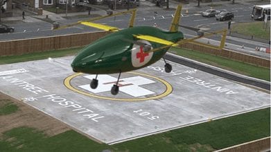
With the growing popularity of autonomous delivery over the years as technology evolves and the demand for high-speed delivery increases, we have produced a solution that has the potential to change and save the lives of many. The world needs technology like SUAVECITO, our UAV design, more than ever, especially with the current state of the world in 2021 throughout this global pandemic. With its ability to deliver medical equipment in all weather conditions, at very high speeds, and without the need for a direct pilot, SUAVECITO is the future of medical equipment distribution.

