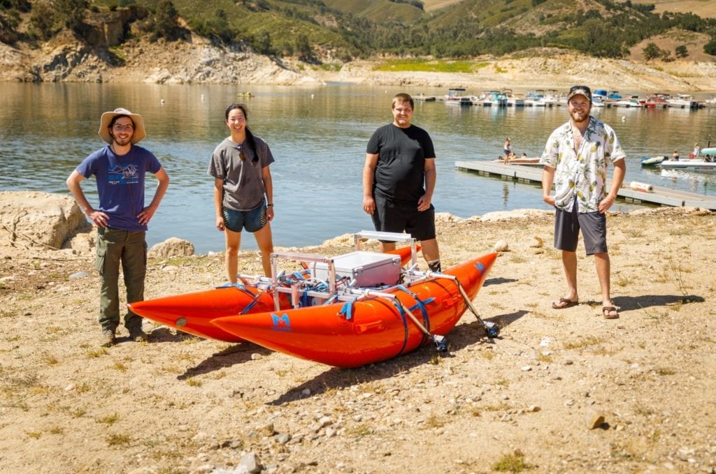
Our Team - Sea Cubed

Andrew Fleming
Technical Lead
Andrew is fourth year mechanical engineering student. Originally from San Diego California, He enjoys hiking around SLO, cooking, and playing video and tabletop games. During his time at Cal Poly he has been involved in both the Cal Poly Racing Formula SAE team and the Mustang Marching Band. He has loved his time at Cal Poly but is looking forward to starting his career as a mechanical engineer.

Kahye Yu
Project Coordinator
Kahye is a fifth year mechanical engineering student. Coming from Kodiak Alaska, she’s always enjoyed being outdoors. She likes to stay busy fishing, hiking, or biking around the SLO area. She has enjoyed staying active and being involved in the rugby club on campus for the past four years. Her time at Cal Poly has been rewarding and she will miss everything it has to offer after graduation.

Jacob Davis
Quality Lead
Jacob is a fifth year student studying Mechanical Engineering with a concentration in manufacturing. Originally from Roseville California, He loves to explore his surroundings with a weekly hike and relax at night with a Discworld novel. He has been involved with CAPED on campus and has truly loved his time at Cal Poly. After graduation he hopes to have a career in themed entertainment.

Luke Vickerman
Design Lead
Luke is a fifth year mechanical engineering student. He grew up near Vail Colorado and spent his summers rafting, and winters skiing. Studying Engineering at Cal Poly has grown both his technical and hands on skills, which are reflected in this capstone project. Spending the past few years on the central coast has been an amazing opportunity for him and he is looking forward to coming back in the future!
Our Project's Videos
Our Project's Digital Poster

This project is sponsored by Lawrence Livermore National Laboratory (LLNL) and Engineers Paul Nyholm and Sam Fuller.
Background
LLNL's Current rafts
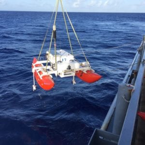
LLNL has a fleet of rafts that are deployed from a ship into the ocean for several days before being retrieved. While on missions the rafts generally loiter around specific locations collecting data. The rafts are 14ft by 8ft in size and weight over 2000lbs. Because of their size, they need to be moved using a crane and transported in shipping containers. This makes it difficult for Lawrence Livermore Engineers to test raft improvements and deploy them in different parts of the world.
Problem Statement
Lawrence Livermore National Laboratories needs a better craft to deploy on their missions because their current rafts are large and bulky, making transportation, deployment, storage, and improvement difficult.
Specifications
After multiple discussions with Lawrence Livermore Engineers about what they wanted in a raft redesign, we compiled the following specifications:
- Weight of under 200 pounds
- Collapsed size that can easily fit onto a pallet or shipping crate
- Average footprint of 4ft x 7ft
- Payload capacity of at least 10 pounds
- At least two motors
- Raft speed of five feet per second
- Total battery life of at least two days
- Lifting method contacts raft at two points or less
- Final design cost under $15,000
Ideation / Prototyping
With our specifications in mind, we moved to ideation. Our ideation sessions included brainstorming, concept modeling, and collaborative drawing. We mixed the best ideas together in various ways and selected the idea that we felt would best meet and exceed the specifications.
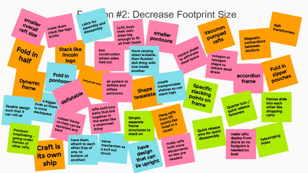
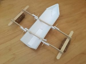
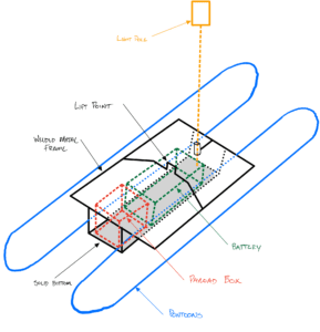
The ideation process eventually led to a catamaran design with two rubber pontoons. The aluminum frame supports the pontoons and supports and carries the payload box and battery.
Concept Prototype
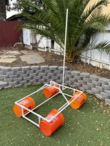
To understand the scale of our design, and to determine if it would be achievable, we built a concept prototype with PVC tubes. This gave us an understanding of where we might encounter problems during our design process and how to avoid them. The concept prototype also helped us to understand the size of the components that we would need to purchase for the final design.
Concept CAD
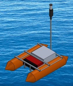
To further refine our concept design and work out the best layout for the battery, payload box, and light pole we made a concept CAD model in SolidWorks with major components and a rough frame. We were able to use this model to see how moving components effected the location of the raft’s center of gravity, which plays a major role in raft stability and lifting.
Frame Design
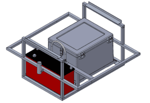
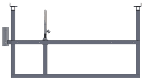
When designing the frame, we allocated space between the pontoons for the payload box and battery. The sizes of these components provided a minimum frame width. To ensure that the frame would fit in a shipping crate or pallet, we kept the length of the frame as short as possible. Our goal was to have a single lift point, so we modeled the components in SolidWorks and moved components around until the raft’s center of gravity was directly under it.
Raft Stacking
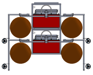
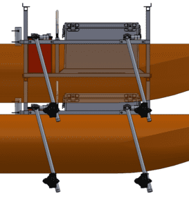
To help reduce the average frame size and make storage more efficient, we wanted to stack rafts atop one another. To do so, we included an upper deck for subsequent raft frames to rest on. This also provided space so that a stacked raft’s pontoons would not rest on those below or interfere with the motor mounts.
Analysis
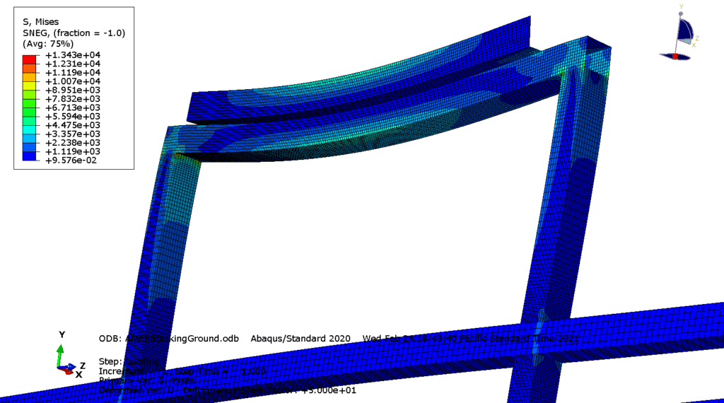
Finally, we needed to demonstrate that this frame design would support the expected loads in the ocean. We first performed hand calculations on all frame members for initial sizing. Since our frame was complex and we were using welded joints, we created a Finite Element Model to better understand where the locations of highest stress were. We looked at three different loading cases to verify that the frame could withstand operation in the ocean.
Motor Mount Design
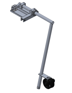
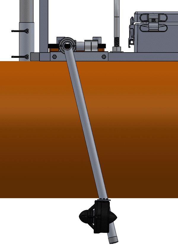
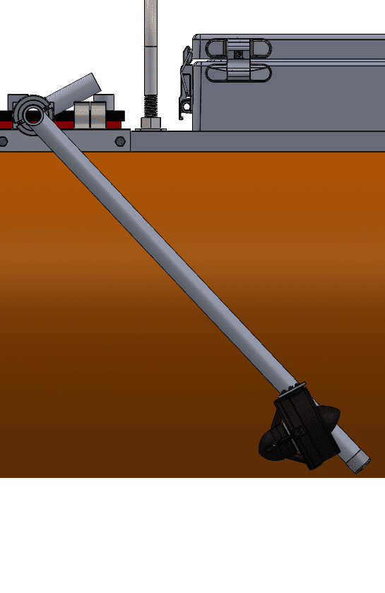
The raft’s thrusters need to reliably sit below the waterline while it is deployed, even in rough seas. Additionally, since the raft needs to rest on the pontoons when out of the water, the thrusters need to move upward to prevent resting the weight of the raft on them.
We considered multiple methods of actuation that would move the motors upward when the raft was placed on the ground, while also resisting the torque created by the thruster running in forward and reverse. Accommodating these three functions in a way that was reliable and could accommodate stacking of the rafts was a major challenge of our design.
We considered linear sliding and four-bar linkage methods, but we ultimately settled on rotating motor arms. The motor arm geometry prevents the arm from rotating under forward thrust, while clips hold the arm and prevent it from rotating under reverse thrust. When the raft is lowered onto the ground, the force on the arms pop them out of the clips and allow them to rotate freely out of the way. The angle of the motor arm allows for this kick-up action, as well as preventing interference between motor arms when stacking.
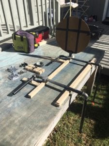
Motor Mount Prototype
We built a structural prototype of our motor mount design to test and refine our concept. We purchased and tested a variety of clips to find ones strong enough to withstand full reverse thrust. Our structural prototype gave us several insights into how to improve the system before implementing it into the final design.
Final Design
Specifications:
Total Weight: 189 lbs.
Weight Without Battery: 122 lbs.
Max Footprint: 9.1 ft. x 5.5 ft.
Shipping Dimensions: 4ft x 4ft x 3ft
Top Speed: 5 ft/s
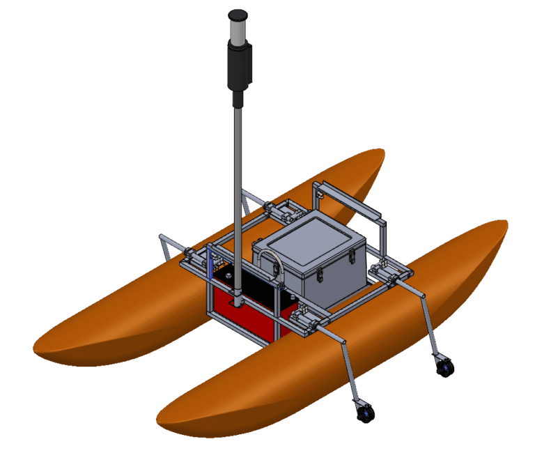
Key Features
Stackable (3 high)
Adjustable Motor Orientation
Forward and Reverse Thrust
Single Lift Point
Major Components
Welded Aluminum Frame
Inflatable Rubber Pontoons
Rotating Aluminum Motor Mounts
Blue Robotics Thrusters
Fiberglass Payload Box
Lithium-Ion Battery
Fiberglass light Pole
Manufacturing
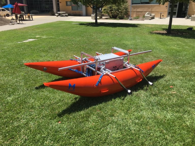
The frame and motor mounts were manufactured by the team in the Cal Poly Machine Shops. The stock aluminum was cut, drilled, waterjet and welded to produce the frame and motor mount assemblies. Fasteners and straps were used in the final assembly to join all the completed components together.
Since shop time was limited by Covid-19, we chose to use waterjet brackets and fasteners in place of welds to join some sections of the frame together. This reduced the overall number of welds on the frame that our team would have to perform without significantly sacrificing our frame’s performance.
Testing
We performed three major tests on the raft. One to ensure the payload box was waterproof after modification, one to measure the speed of the raft, and one to measure raft assembly time.
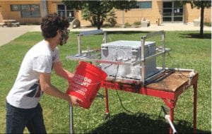
Waterproofing Test
Before taking the raft out on the water, we splashed water on the payload box to check for leaks around the holes we cut for electrical cable routing. When we found some leaks, we sealed them with silicone sealant so we wouldn’t damage the electronics used to control the raft.
Speed Test
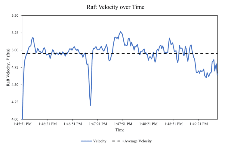
We took the raft to Lake Nacimiento to ensure that the raft floated and maneuvered properly. While there we performed tests of the raft’s top speed. Using LLNL’s control software we gave the raft start and end GPS coordinates and raced it at full power between them. Using logged GPS data we calculated and graphed the rafts speed over time as shown below.
Assembly Test
Finally, we assembled and disassembled the raft multiple times to make sure that it doesn’t take too long to setup or tear down, since this was a goal from our sponsors. Fully assembling and disassembling the major components of the raft took four people roughly 20 minutes, but preparing an assembled raft for deployment took one person around 45 seconds.
Future Work
While there are some improvements to make to the design, the raft performed well on the water and exceeded most of our sponsors specifications. Overall we are very pleased with the design and execution of the verification prototype.
Next Steps
This design was the first prototype iteration on a raft redesign. We expect that LLNL will continue to test this design and improve on it in further iterations. As a team we did our best to understand user requirements, but ultimately LLNL will make changes based on their own experiences using it. We believe that our design is an extraordinary starting point for LLNL and will hopefully lead to greatly improving their testing and research capabilities
Manufacturing Photo Gallery
Testing Photo Gallery
Acknowledgements
Our team would like to thank our project advisor, Dr. Peter Schuster, and our sponsors Paul Nyholm and Sam for their support and guidance on this project. We would like to thank Brittany McKim for her role in coordinating part purchasing and delivery. We would also like to thank Eric Pulse and the Cal Poly Machine Shops for maintaining a working shop environment despite this year’s limitations, since access to the shops was critical to our project’s success.

