Our Team

Darya Darvish
Mechatronics & Testing
Darya Darvish is a mechatronics engineer from Los Altos, California. His main roles in the project were control system design, embedded programming, and test analysis. This project allowed him to apply his critical thinking skills to a multidisciplinary problem.

Charlie Glenwright
Analysis & Design
Charlie Glenwright is a Mechanical Engineering major originally from Palo Alto, California. His roles in the analysis and design of the electromagnetic actuator combined his interests in computer modeling and all things automotive.

Nicholas Olesh
Analysis & Project Management
Nick is from Santa Clarita, California. He is a Mechanical Engineering major with a concentration in Mechatronics. His main roles were analysis and project management, and he hopes to explore these further throughout his career.

Tim Wills-DeTone
Manufacturing & Testing
Tim Wills-DeTone is a Mechanical Engineering major from Santa Cruz, California. His main roles were manufacturing and test engineering, both of which reflect his interests in fabrication and mechanical design.
Acknowledgements
This project was sponsored by two research professors at Cal Poly SLO, Dr. Eltahry Elghandour and Dr. Ashraf Elbarbary. It also could not have been completed without the guidance of our advisor, Sarah Harding, and the assistance from electromagnetism professor, Dr. Majid Poshtan.
Our Project Videos
Our Project's Digital Poster
Problem Statement
Research and design a purely electromagnetic actuator that could replace the cam mechanism on modern-day automobile engines. This includes the analysis, building, programming, and testing involved to have the actuator accurately match the motion profile of the cam and engine.
Design Constraints
- Actuator is solely electromagnetic
- Must be able to fit under the hood of a car
- Have an opening time below 15 ms
- Have a force above 885 N
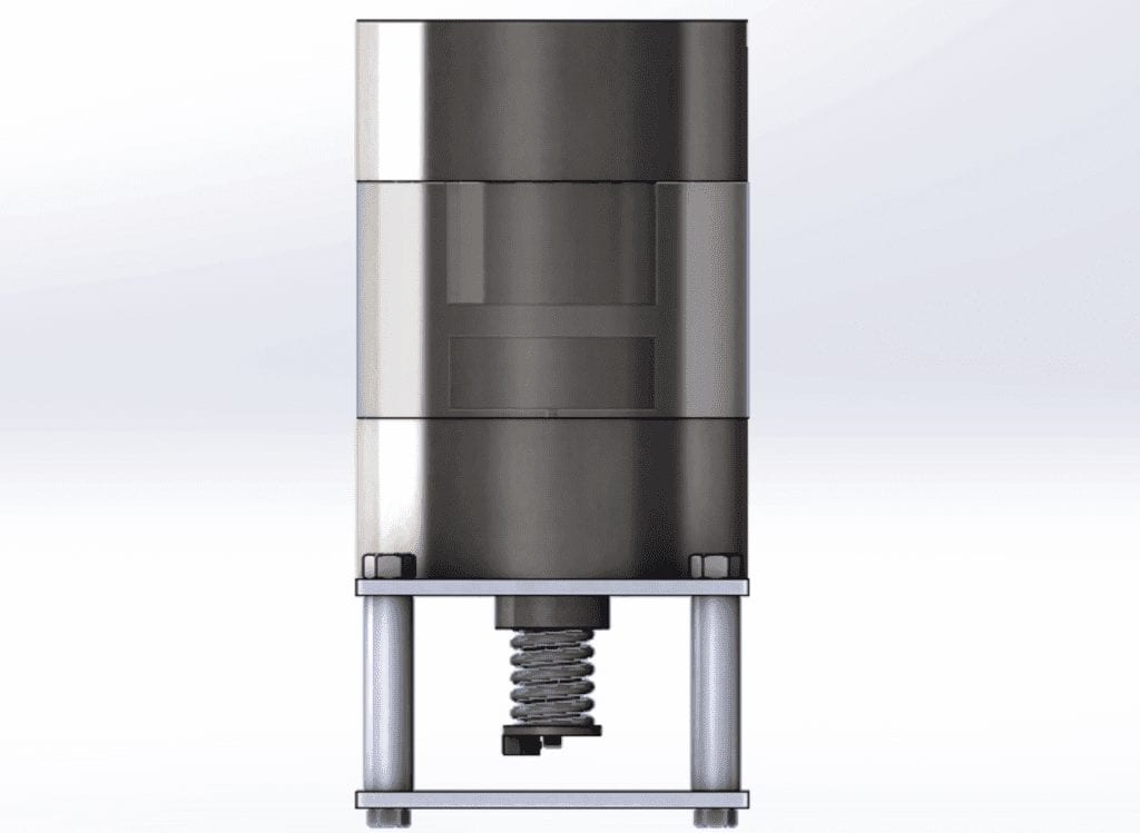
Actuator Layout
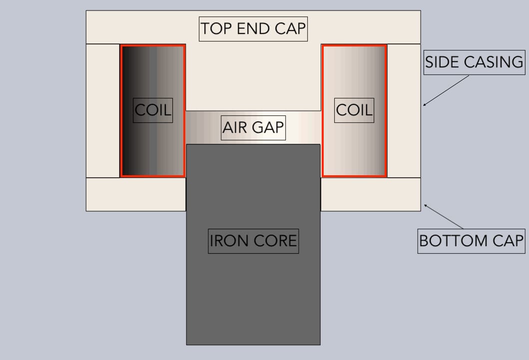
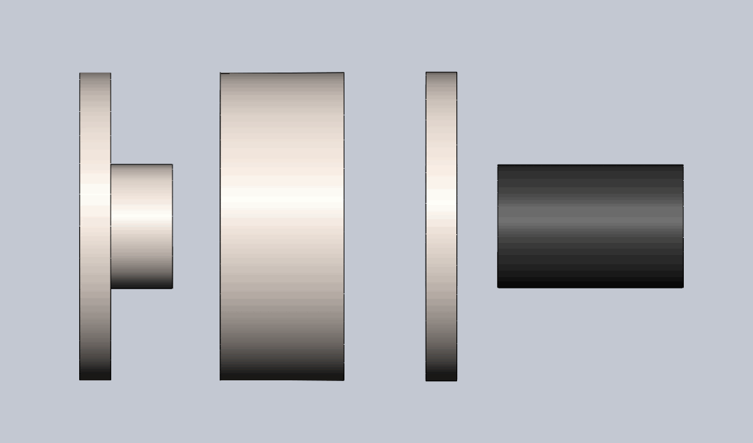
A moving core, solenoid design was used for the following reasons:
- High force/frequency capabilities
- Easy to connect the moving iron core to a rocker arm
Material choices:
- Iron was chosen for core due to high permeability
- Steel chosen for casing as it is encloses the magnetic field and is cheaper in bulk than iron
- Copper wire chosen for its low resistance and commonality in solenoid applications
Design specifications:
- Power source – 24V , 1000W
- Wire size – 14 gauge wire
- Number of Turns – 420
- Solenoid diameter – 6 inches
Controls Layout
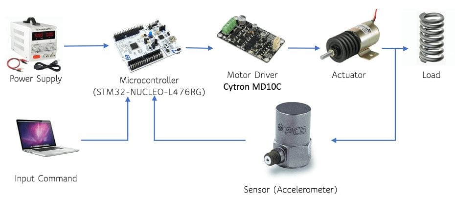
A control system is needed to control the current flowing to the actuator at different frequencies.
Test Stand
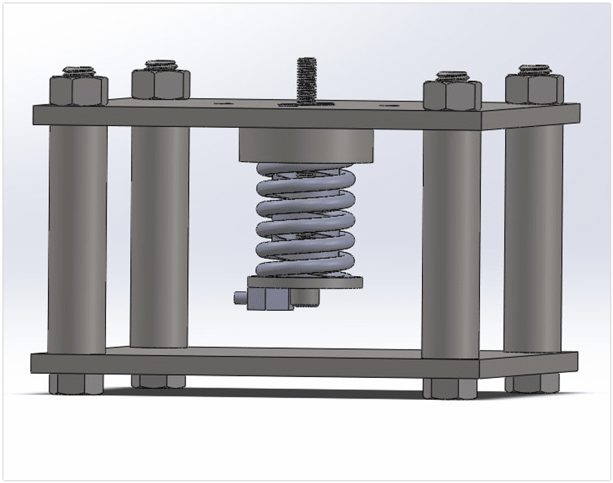
To verify our actuator, a test stand was designed and built. The actuator could be mounted on top of the test stand with a bolt attaching to the core. An accelerometer attached to the end of the bolt and a data acquisition system would provide data such as the time, acceleration, and, since we know the mass, the force produced.
Design Concept
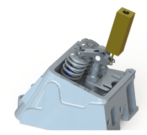

This project was sponsored by Dr. Elghandour and Dr. Elbarbary.
Analysis
To model and analyze the actuator, various tools were used. The main programs used in analysis were Finite Element Magnetic Method (FEMM), MATLAB, and Microsoft Excel.
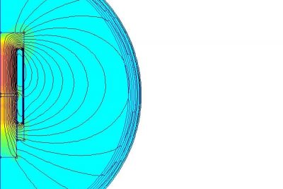


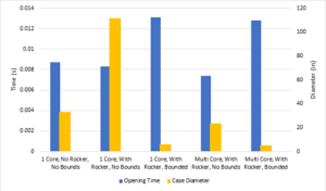
FEMM was used in conjunction with MATLAB to create an optimization program. A program was written in MATLAB to change design variables in an FEMM actuator model. Outputs were then plotted in MATLAB to compare forces and opening times.
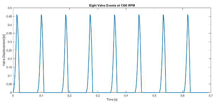
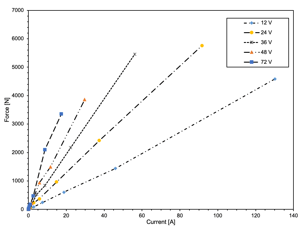
Along with the simulation, an analytical solution was found using equations derived from several research papers. This analysis was done predominantly on Excel.
Manufacturing Process and Components
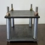

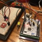
Our team was able to complete the manufacturing of a custom test stand and the control system of our actuator. The test stand was designed with ease of manufacturing in mind and required only minimal time in the Cal Poly Machine Shops on a drill press and belt sander. The assembly of the control system required soldering and wiring connections.
Design Verification
Due to unforeseen circumstances surrounding COVID-19, our group was unable to fully manufacture and test our designed actuator in Spring 2020. Instead, we bought a small linear actuator and tested our control system.
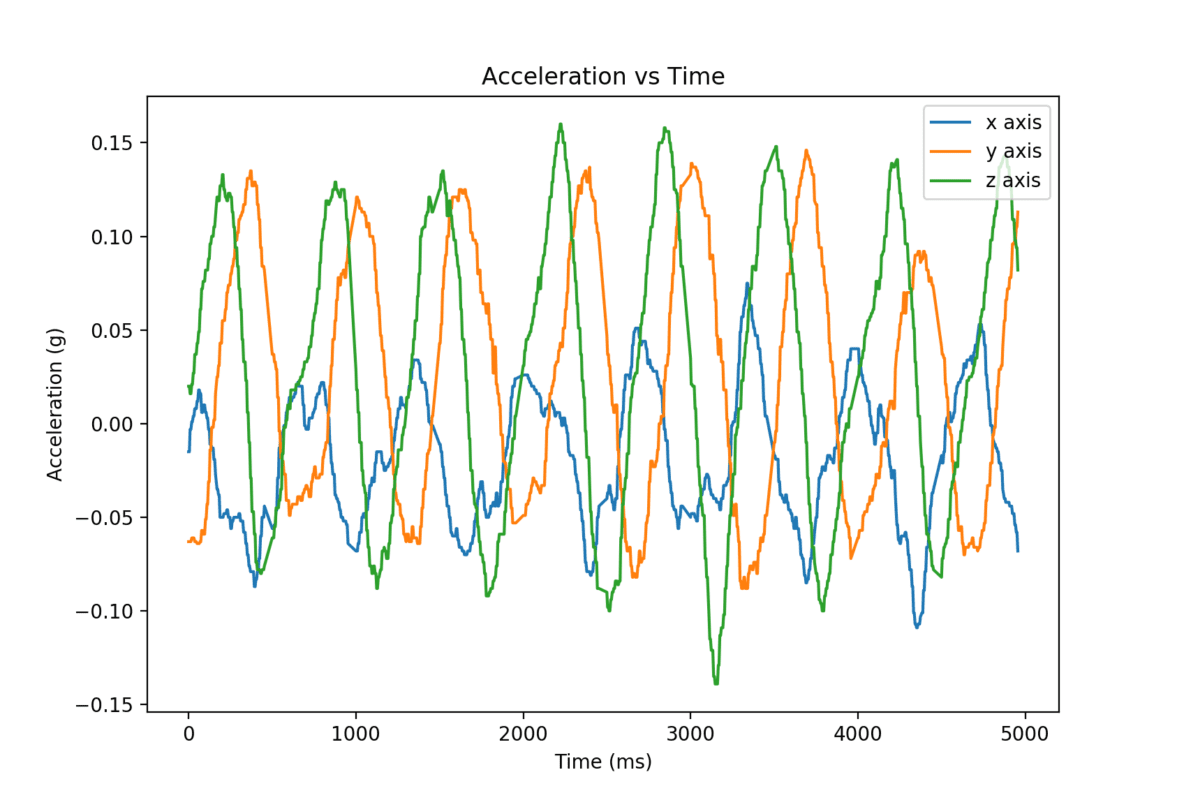
Controls Test – A special circuit was designed incorporating a diode and high power MOSFET transistor in order to ensure safety. While the accelerometer data varies drastically from what we would have gotten for our actuator, this test verifies our control system. A program running on a PC prompts the user for a number of cycles and a frequency and send the information to a microcontroller. The microcontroller accurately accepts the input and triggers the actuator, as well as reads data from the accelerometer via the I2C communication protocol. The microcontroller then writes the data back to the PC which plots the data, which can be also be saved to a csv file for further analysis. Future improvements to the control system include incorporating a temperature sensor to trigger a safety shutdown due to overheat as well as improved digital signal processing.
Final Design
Specifications
Theoretical force – 965 N
Theoretical opening time – 14ms
Weight – Core: 1.9lbs, Total: ~40lbs
Dimensions – 6in outer diameter, 6in height
Power Consumption – 898 W
Actuator Components
- Steel Actuator Housing
- Cast Iron Actuator Core
- 14 AWG Copper Actuator Coil
- Steel Test Fixture Assembly
Control System Components
- NUCLEO Microcontroler
- Cytron Motor Driver
Future Application
This project was done mostly as a research project to determine the plausibility and efficacy of an electromagnetic actuator for engine applications. Although we ordered all materials, we did not manufacture or fully test the actuator. This may be completed by a future senior project group, as well as possible adaptations.
Conclusions
Conclusions and things learned from project:
- The speed of electromagnetic actuators are not adequate for engine valve train applications
- The relationship between the mass and saturation limit of the iron core prevent valve opening speeds required for a gasoline engine (approx. 3ms)
- The major limiting factors in EM actuator feasibility are size and power consumption
Recommendations
Improvements to be made if actuator were to be re-designed:
- Utilize fluids or pneumatics in design to achieve higher force
- Custom high performance voice coil actuators may be able to achieve faster actuation speeds

