
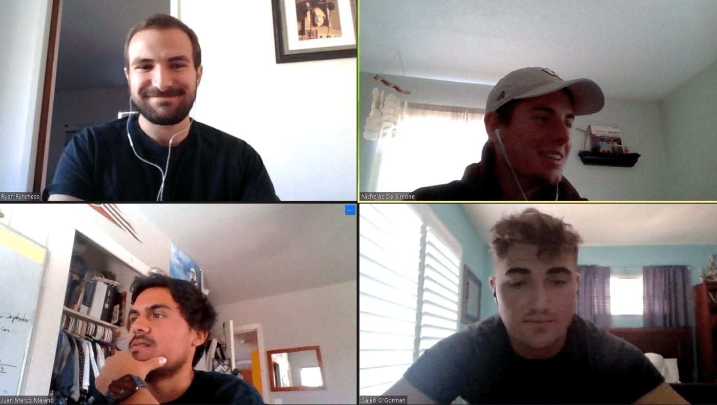
Ryan Funchess
Controls Master

Nick de Simone
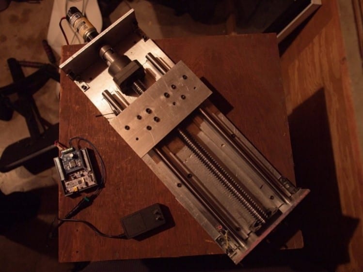
HARDWARE GURu

Juan Marco Majano
SOLE POINT OF CONTACT

Caleb O'Gorman
fRONTEND Wizard


This project is sponsored by Dr. Xing of the Cal Poly Mechanical Engineering Department
