Structures Team
The Structures Team is responsible for the physical structure of the environmental chamber and the mounting and integration with the tensile testing machine.

Erik Soldenwagner
Structural Team
Erik is a mechanical engineering student concentrating in manufacturing. He gained valuable experience working with composites while working with the chamber structure and enjoys working with advanced materials.
Lauren Schirle
Structural Team / CAD
Lauren is a mechanical engineering student planning on graduating in December 2021. She has interests in composite materials, manufacturing, and design; which she enjoys having hands-on experience in from Formula SAE as well as this project.

Michael Ingel
Structural Team
Michael is a mechanical engineering student planning on graduating in June 2021. His interest include design for manufacturing in the biomedical or defense space.

Austin Marshall
Structural Team
Austin is a mechanical engineering student with a general concentration with a focus on renewable energy. He has gained lots of practical experience working with composites in heated structures and his interests include heat transfer and renewable energies.
Controls Team
The Controls Team is responsible for the components and controls of the heating and cooling elements in the environmental chamber.

Mitchell Carroll
Mechanical Design/electronics
Mitchell Carroll is a mechanical engineering student in the general concentration. He has an interest in mechatronics and has enjoyed being able to learn new skills in that area while working on this project.

Cameron
Ngai
control wizard/coder bro
Cameron Ngai is a mechanical engineering student with a concentration in mechatronics. He enjoyed developing the controller for the chamber.

Trent Hamilton
electronics/coder bro
Trent Hamilton is a mechanical engineering student with a minor in computer science. He gained an interest in mechatronics through working on the Cal Poly Microgrid project. He enjoyed working on the mechatronics related aspects of the chamber.

Jack Molitor
mechanical design/integration
Jack Molitor is a mechanical engineering student with a general concentration. He plans on graduating in December 2021 and has gained an interest in the automotive industry through experience with Formula SAE.
Acknowledgements
Thank you to everyone who helped with our project. We would like to give a special thanks to Eltahry Elghandour, Marius Jatulis, Peter Schuster, Christopher Pascual, Mona El Helbawy, and all the technicians at Mustang 60 and the Aero Hangar. Thank you to CP Connect for the gracious funding in this project.
Project Videos
STRUCTURAL DESIGN OVERVIEW
CONTROLS SYSTEMS OVERVIEW
Digital Poster
Problem Statement
Dr. Elghandour requested a lightweight, affordable environmental chamber that interfaces with the Lloyd LD50 tensile test machine. This environmental chamber needs to weigh less than 50 lbs, easily and repeatably fit on the LD50, and quickly achieve temperatures in a range from 0° to 210°C within a tolerance of ±1°C. This speed is necessary so that multiple tests can be performed in a short period of time and the response of various materials to thermal shock can be tested. This chamber must be controlled by an onboard control panel capable of automatically adjusting heat and cooling rates based on user input.
Technical Design Constraints
- Weight: 50 lbs
- Maximum Temperature Capability: 210 ℃
- Minimum Temperature Capability: 0 ℃
- Maximum Heating/Cooling Rate: 15 ℃/min
- Temperature Accuracy: ±1℃
Design Direction
Controls systems
- Heating Scheme
- For heating the chamber, we considered several options but eventually decided to use resistive heating elements in the form of strip heaters. We decided to use these because of their commercial availability and their configuration within the chamber.
- Cooling Scheme
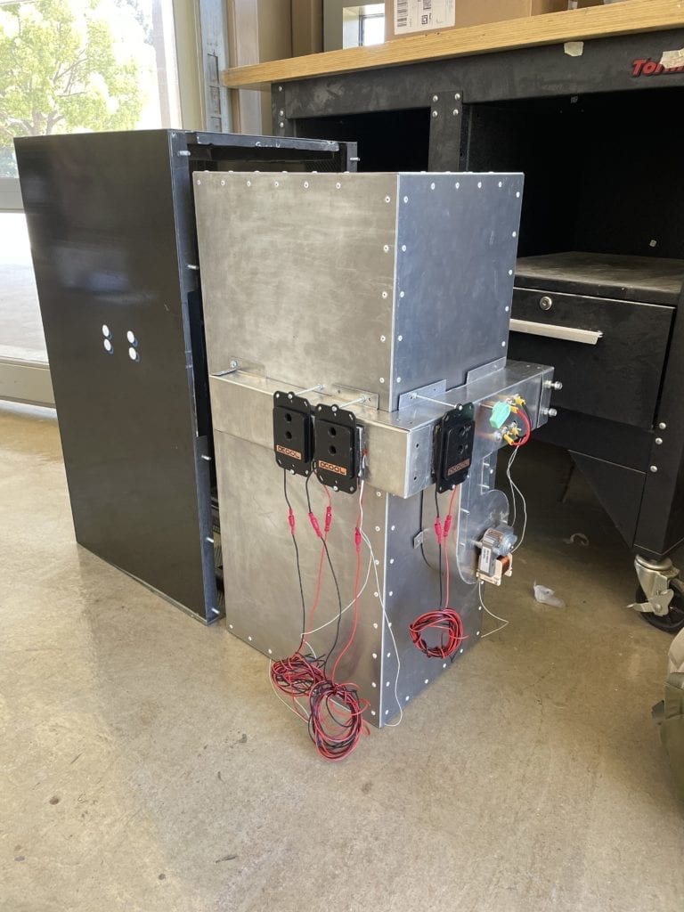
- For the cooling system, we have elected to use solid state cooling devices know as peltier devices. These devices work on the thermoelectric principle and are capable of generating a thermal gradient across their two surfaces. The waste heat from the hot side of of the peltiers is rejected using a computer water cooling system.
- Airflow
- To circulate the air within the chamber, we have designed a system of ducts. air from the fan flows through a switch in the ducts that switches the airflow between a heating and cooling scheme.
- Controller Design
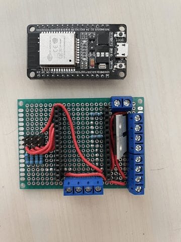
- To control the various componenets within the chamber, wedecided to use two ESP32 microcontrollers (MCUs). the first MCU handles running the controller code as well as interfacing with the hardware in the system. The second MCU hosts a web server on a WIFI network that interfaces with he user. the web server will display the current state of the chamber with temperatures for the inner chamber as well as the various elements. The user will also enter setpoint temperatures through this interface.
Structures systems
- Internal Chamber
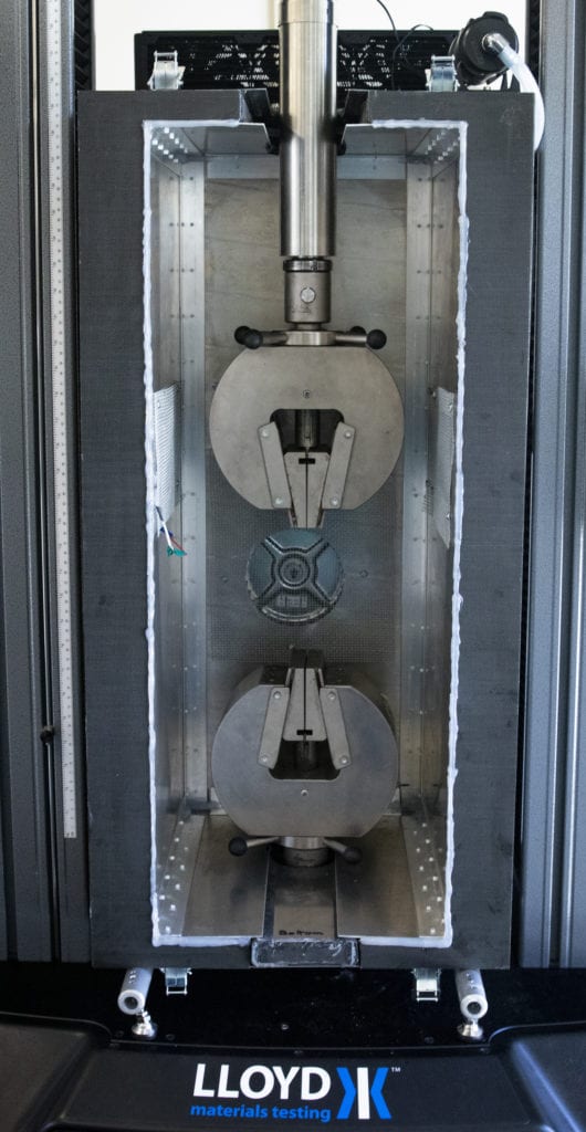
- The chamber structure is a shelled design, with the internal chamber made from 5052 1/16th-inch thick aluminum. This material was chosen because of its strong resistance to heat deformation as well as to give the chamber a rigid structure that the heating and cooling elements can be fixed to. Individual panels were water-jetted to size, including cuts for ducting holes, slots for the LD-50 machine arms, and rivet holes. The panels were riveted to aluminum L-brackets to give the chamber its shape.
- External Chamber
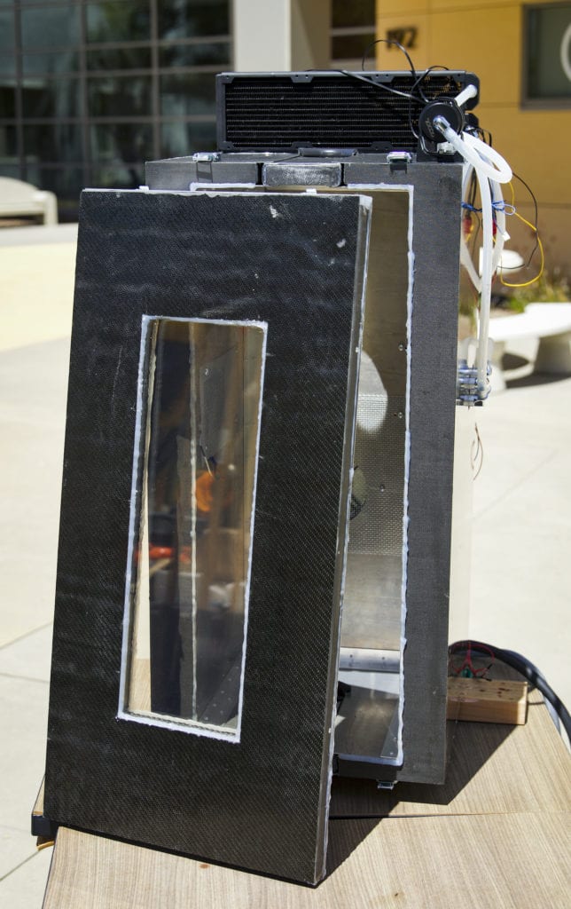
- The external chamber structure is made from custom composite sheets made from carbon fiber and fiberglass provided by the Cal Poly Composites Lab. Composite was chosen for its ability to handle the physical and thermal loads experienced during live testing while remaining lightweight. The shape was designed to fit controls system components while still fitting within the size constraints of the LD50 tensile testing machine.
- Insulation
- The chamber insulation is designed to resist the high temperatures of proposed testing conditions while limiting thickness to avoid exceeding the size constraints set by the LD-50 machine. Pyrogel, a hybrid fiberglass-aerogel insulation, was selected as the main insulation type. Exhaust manifold sheeting was also purchased and repurposed; the aluminum-coated fiberglass sheet provided extra insulation as well as radiation protection. Pyrogel was sandwiched between manifold sheeting layers, with the resulting “pillows” cut to shape to conform to the chamber’s slots, ducts, door window, and other components.
- Door
- The door is split into two main parts and internal face made out 5052 1/8” thick aluminum panel which was then affixed to our carbon fiber/fiberglass layup using rivets and epoxy on both aluminum edging and custom carbon fiber L-brackets. Additionally, both pieces feature inlaid 3/16” ceramic glass and custom insulation. These features allow the user to easily and safely handle installation/removal of the door and the ability to monitor their test sample during experiments.
- Rails
- The rail system is designed to be a guiding and supporting system for the chamber as it fits on the LD50 machine. Aluminum piping was cut to size, with holes tapped for ball-joint feet to thread into as structural support. The rails are also bolted to the LD50 for added fixturing and are leveled to ensure an accurate and repeatable process of putting the chamber onto the machine.
CAD
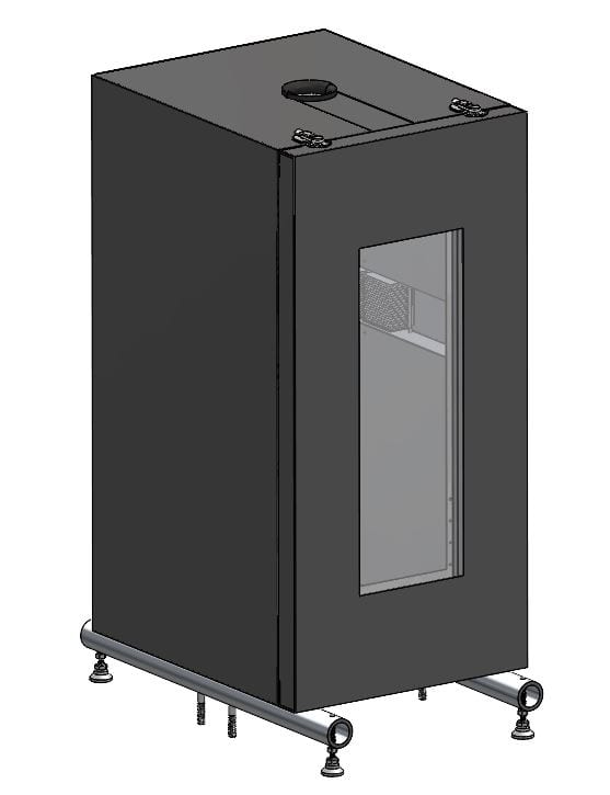
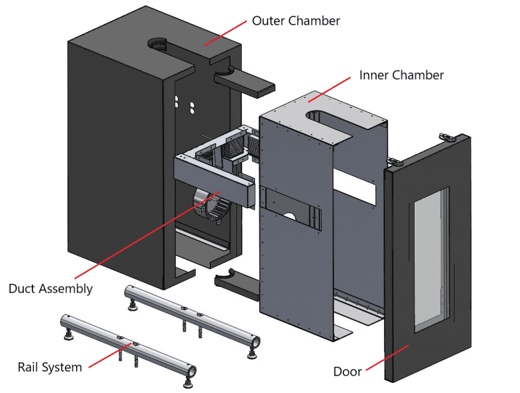
Pictured above in Figure 1 is the CAD model of all structures components as well as the heating/cooling duct assembly. The exploded view pictured in Figure 2 depicts a clear view of each individual subassembly: the inner chamber, outer chamber, ducts, rail system, and door.
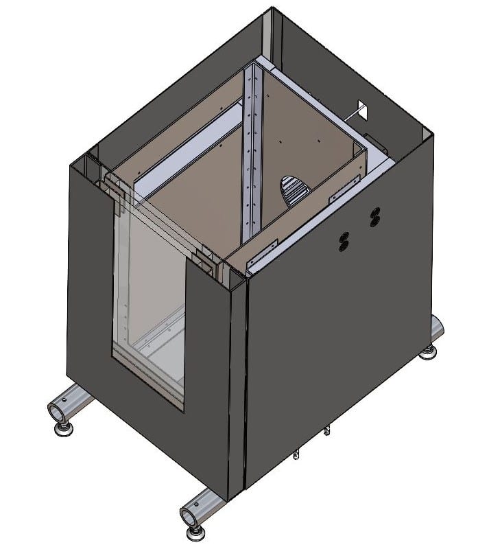
The section view in Figure 3 above shows the internals of the assembled chamber. The empty space in between the aluminum inner chamber and composite outer chamber allows room for insulation material and radiation shielding, which is not modeled. This view also shows the assembly of the door with two glass panels mounted and sealed via brackets, and additional empty space for more insulating material.

Cal Poly Mechanical Engineering
This project is sponsored by Dr. Elghandour and the Cal Poly Composites Lab
Analysis and Modeling
Control Scheme
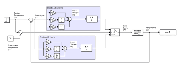
Control Architecture:
The above block diagram shows the overall structure for the controller. It takes the overall forms of a PID that switched between sets of gain constants depending on a heating scheme or cooling scheme. The controller is informed by a series of thermistors that input the temperature of the system at various points. The temperature values at the cold side of the peltiers, the heating element and ambient temperature were logged in addition to the internal chamber temperature values to increase the accuracy of the model. each of these temperatures were filtered using a Kalman filter that compares the temperature reading to one that is predicted by the model of the system. This filtering technique ensures that the system controller is informed by the most accurate information.
Composite Material Testing
Material Strength Characterization:
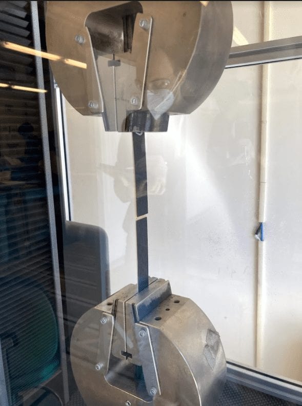
Before deciding on a particular carbon fiber and fiberglass to use for the construction of our external chamber, we needed to characterize the material strength of carbon fiber for our outer chamber. We tested the tensile properties of two different carbon fibers available to us: one roll was a plain weave that was slightly dried out and the other was a slightly thicker twill weave from Boeing. We tested using an LD 50 Tensile Testing Machine and determined that while both samples performed above the forces, we expected to experience reality. The twill sample outperformed the other sample by about five thousand Newtons.
Heat Bleed Testing
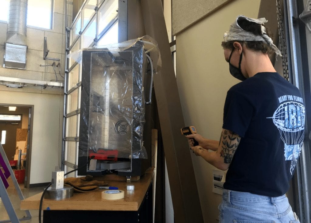
Preliminary heat bleed testing was first performed on structural prototype to investigate the planned measurement process. This test was performed as a preliminary proof of concept, being built out of thin aluminum sheet metal and insulated with a simple hemp-silicon material. Heat was applied to the internal wall with an electric heating pad set to its maximum temperature of 190 °C and a thermocouple was used to take measurements at the internal and external wall locations. Exterior walls were sampled with either convection, conduction, or a combination of the two to investigate how different conditions affected temperature readings.
Manufacturing
Structures
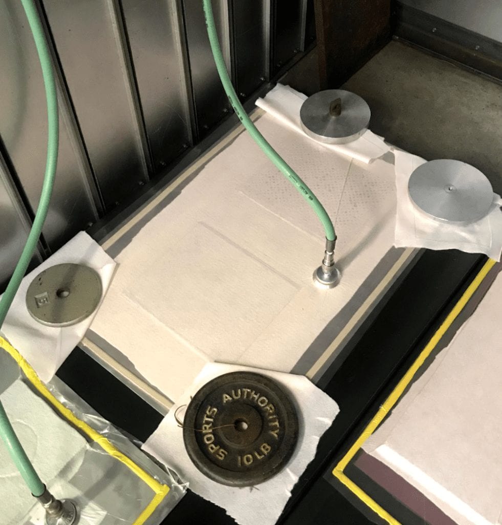
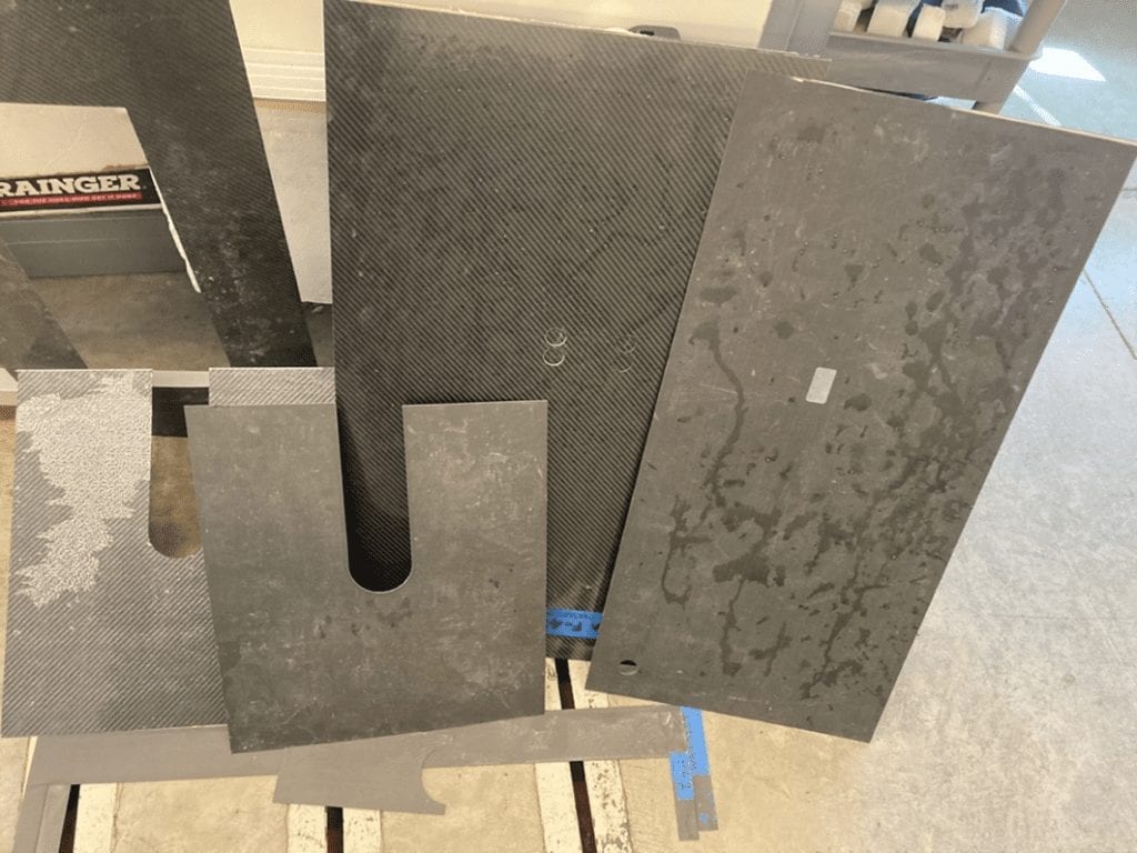
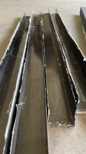
Composite outer walls were custom manufactured using pre-impreginated carbon fiber and fiberglass sheets. Flat panels were laid up and cured in the 192-135 oven, then cut to shape using waterjet. Outer walls were then assembled using epoxy advesive and composite L-brackets that were also custom made.
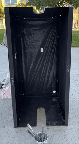
The aluminum inner chamber walls were similarly cut to shape using the waterjet, then assembled together using rivets and aluminum L channel.
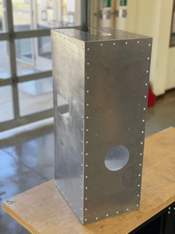
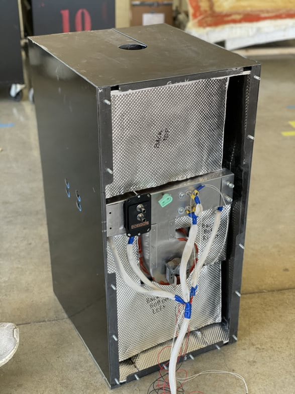
The inner chamber was then placed into the outer chamber where it is supported on composite channels. Insulation material made of radiation shielding and aerogel insulation was placed around the inner chamber and duct components. Finally, all gaps were sealed with RTV silicon.
The door assembly was manufactured by attaching an aluminum plate and composite plate together using bonded and riveted aluminum and composite brackets. On the inside faces, two glass panels were mounted using aluminum bracket. Space between the aluminum and composite sides of the door was then filled with insulation material. Finally, latches were attached to the outer sides of the door and outer chamber using rivets and epoxy adhesive.
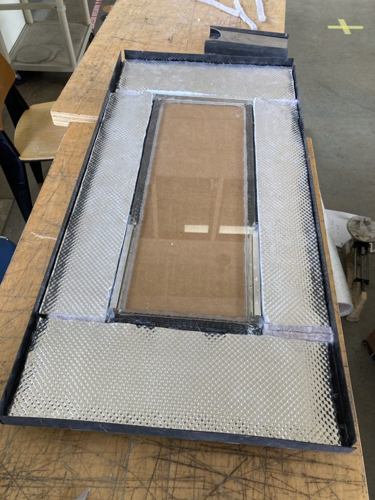
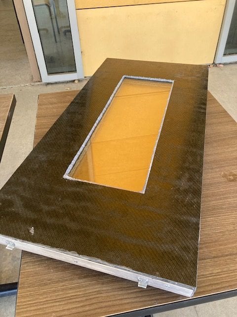
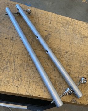
Rails were manufactured by cutting aluminum tube stock to length, then drilling holes for threaded foot stands and bolts to mount the rail assembly to the LD50
Controls
- Ducts
- For the controls side of the system, the manufacturing mainly consisted of selecting off-the-shelf components and designing a system that allowed the components in interface with each other in a meaningful way. The main structure that needing to be manufactured was a system of ducts that directed airflow to the chamber over certain components. These ducts are constructed of 0.032″ aluminum sheet metal that was waterjet cut and folded to the appropriate shape.
.
- Circuitboard
- The control circui for the chamber was constructed using a through hole development board. this board was designed to contain the switching circuitry and sensing circuitry for all of the low current components. To manufacture this board, we fir created the traces with solder, and then soldered on and connected the necessary components.
Final Prototype
Specifications
Weight : 49 lbs
Weight without door: 37 lbs
Dimensions 15.6” X 16” X 34”
Custom Components
– Carbon Fiber/Fiber Glass Panels
– External Chamber
– Internal Chamber ( 5051 Aluminum)
– Insulation (Aerogel surrounded by Heat Shielding)
– Rail assembly
– Door assembly including glass viewport
Purchased/Provided Components
– High Temp Silicone Sealant (RTV)
– Door latches
– Carbon fiber pre-preg material
– Fiberglass pre-preg material
– Magnolia epoxy adhesive
– 3/8” thick ceramic glass
– Aerogel fiberglass insulation
– Heat Shielding
Design Verification
Heat Bleed Test
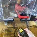
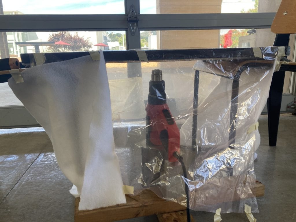
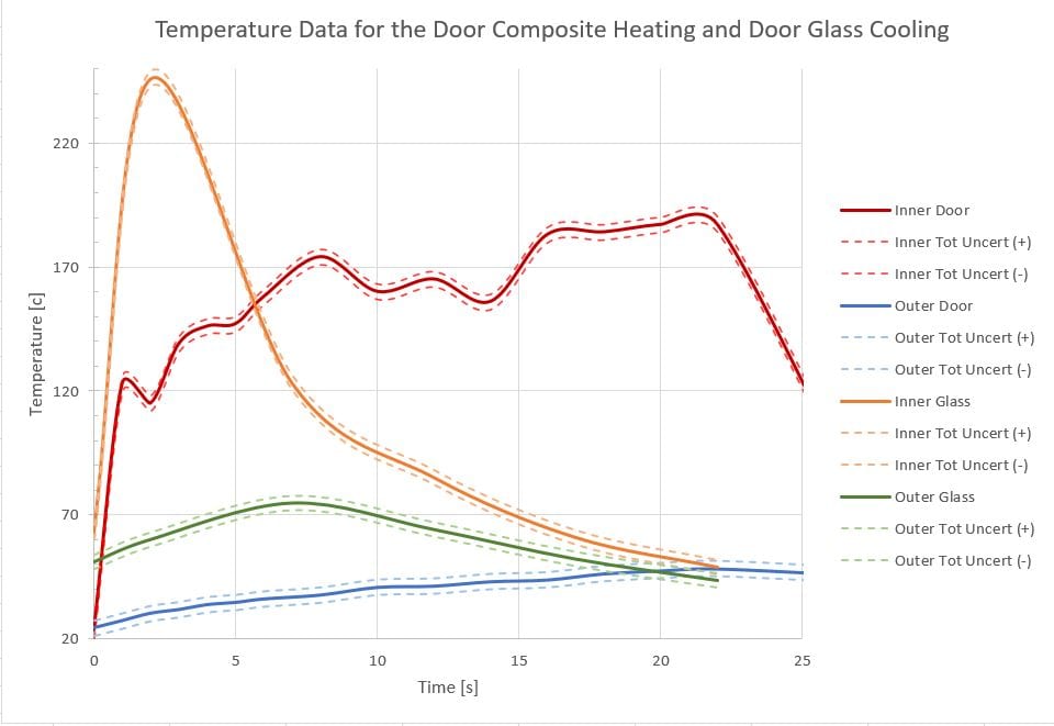
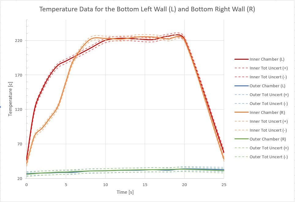
The effectiveness of the insulation and sealing was tested by measuring the heat bleed, by heating local areas of the inner chamber wall surfaces to 200 °C using a standard heat gun. Upon reaching the target internal temperature, an infrared heat sensor was used to measure the local external temperatures of each outer panel at its four corners and at its center. External surfaces remained safe to touch while internal chamber temperatures reached their maximum value, except for the glass surface on the door which reached dangerous temperatures.
Fit Check Tests
The completed prototype was tested on its ease of install and its compatibility with the LD50 machine.
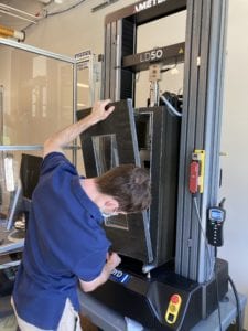
The installation was found to be simple with two people. The door was able to be put on and taken off quickly.
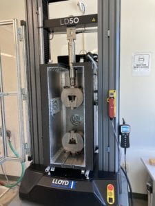
The prototype fits within the machine testing area, including the blast shield enclosure.
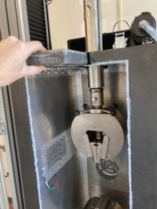
The arms and jaws of the machine fit against the gasket of the chamber and gaps are sealed sufficiently.
Controls Testing
- Component Test
- A major part of the controls system is that integration between various components. In order to ensure that all of the components and the circuitry needed to drive the components is functional, we preformed a component test. This consisted of a simple functions check in which each component was pugged in individual from the other and the intended function was verified. This saved us a significant amount of time when troubleshooting the control circuitry.
- Step Response Test
- To perform the step response test, we created a simple script that runs the heating elements at maximum capacity while logging temperature data from the interior chamber. this test was then repeated for the cooling scheme. This test serves the purpose of validating the maximum capacity and heating/cooling rate requirements. It also allows us to calibrate the control algorithm for the actual system instead of the model.
- Airflow Test
- An important assumption that we made when sizing components was that the fan that we had chose will output the flowrate that we expect. since there were no specifications on the fan that we purchased, we compared it to a similar model to base our calculations on. This test measured the airflow from the ducts to ensure that the air velocity is consistent with the model that we constructed.
- Controller Test
- The final test that we preformed was a controller test. This test proves the function of the control algorithm in the manner that we expect. To preform this test, we ran the chamber with a number of setpoints to test the chamber’s ability to react to disturbances and reach the desired temperature.
Future Changes
Improvements to be made in a prototype re-design:
- -Optimize chamber’s size and weight by reducing material used and utilizing lighter materials
- -Decrease chamber depth to allow more room for wiring and door handles
- Improve tolerances in construction to reduce to reduce the need of RTV sealant to fill gaps
- -Redesign ducts to accept heating elements that will be far more powerful than the current chamber.
Further work recommended for the current prototype:
- -Improve aesthetics by applying topcoat on composite sides
- -Manufacture better quality rails using the current design
- -Construct a support piece that the prototype can sit on in the composites lab when not in use
- -order a custom PCB with the same circuit design to increase the reliability of the chamber.
- -Install the higher power power supply so that all 3 peltiers may be run at once.
- -Design a component that restricts the axial motion of the motor shaft to prevent fan rubbing
- -swap for more powerful heating elements.
- improve web server functionality to include live updates for a graph on internal temperature
