Adaptive Vehicle Control

This is our Final Prototype for our Adaptive Vehicle Control device. We were tasked with creating a device that actuates a clutch pedal. The device accomplishes this by taking user input force at the horizontal pedal and pulling a wire attached to the clutch.

Adaptive Vehicle Control Team

Meet our engineering team!

Brian1

Brian Finger

Project Manager

5th Year Mechanical Engineer General Concentration

Hometown: San Luis Obispo, CA

Hobbies:  Backpacking, Montain Climbing, Soccer

MV2

Maria Vargas

Design Engineer

3rd Year Transfer Mechanical Engineer

General Concentration

Hometown: Vallejo, CA

Hobbies:  Swimming, Tennis, Detecting Metal

Untitled picture

Jake Larson

Structural Analysis Engineer

4th Year Mechanical Engineer General Concentration

Hometown: Sisters, OR

Hobbies:  Surfing, Water Skiing, Rafting Guiding, and Shredding the Gnar

Chris Villa

Design Engineer

5th Year Mechanical Engineer General Concentration

Hometown: Windsor, CA

Hobbies: Sunday League Futbol, Kickboxing, Drawing/Painting

Acknowledgements

Our team would like to thank our Sponsor, Laura Jagels, for giving us this great opportunity, as well as our Senior Project Advisor, Sarah Harding, for helping us throughout the process.

Our Project's Videos

Our Project's Digital Poster

Problem Statement

Laura Jagels, an above the right knee amputee, needs a way to safely and effectively operate a manual car using all of her limbs, because current hand clutch products don’t deliver the original driving experience.

Design Constraints

  • -Be installed/removed from the vehicle in less than 2 minutes
  • -Have a minimum life cycle of 1000 cycles
  • -Allow the user to actuate the break in less than 1 second
  • -Require an actuation force of less than 40 lbf
  • -Must have a planar displacement of less than 1 inch in any direction
  • -Wire must withstand a pulling force of at least 120 lbf

Design Process

Concept Development and Ideation:

  • We began our concept development with the process known as Functional Decomposition.
  • We used Pugh, Morphological, and Weight Decision Matrices which allowed us to determine which concept sketch to use.

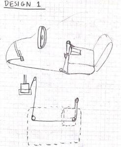
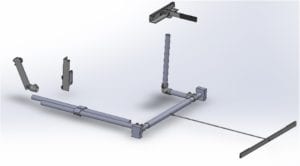
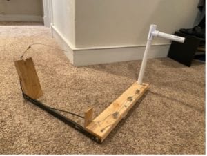
Final Concept Design:

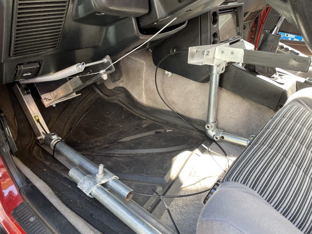
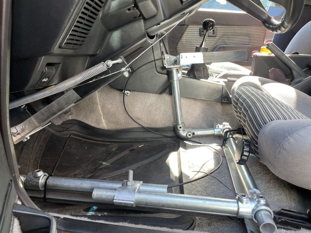
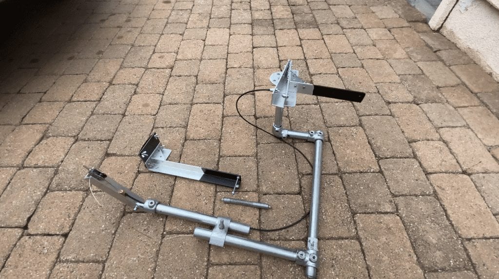
  • Mrs. Jagels operates the device by pressing a pedal in a horizontal direction, which in turn pulls a wire attached to clutch pedal.


Concept Prototype

Concept Prototype Model consists of the pipe lever as the side-to-side pedal actuator and the pulley system on the wooden frame with the wire which would pull the clutch pedal back.

Analysis

Using our engineering analysis, we were able to determine expected loads based on design dimensions:

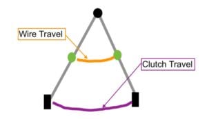
Wire Clutch vs Travel

By assuming the worst-case scenario in which the full clutch pedal travel is 8 inches, we are able to reduce the user input travel down to 4 ½ inches by using the full 7 inches of the angle iron attached to the clutch pedal attachment assembly. This is how we decided on the location of the wire on the horizontal pedal.

Adaptive Vehicle Control

Sponsor: Laura Jagel

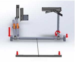
Forces and Moments Applied

We calculated estimates of the forces and moments acting on the device when the clutch pedal is actuated. This gave us an idea of how to attach the components as well as the material we’d use. We found that the structural piping and material we used was enough to take these different load and moments.


Manufacturing

Manufacturing Overview:

Our team designed the Adaptive Vehicle Control device to require no custom manufactured parts. Keeping custom manufactured parts to a minimum has a few benefits in that it is cost-efficient, lowers the risk of certain components, and saves time during the design and analysis process of production. 

Procurement:

We were able to procure all our materials, with a few exceptions, from these four suppliers: Amazon, Ace Hardware, Home Depot, and Lowes.

Manufacturing Subsystems:

The two main tools we used throughout the whole manufacturing process consisted of a hacksaw and a hand drill.

We split up our whole device into five different subsystems:

  1. -Main Structure System
  2. -Seat Bolt Attachment System
  3. -Horizontal Pedal System
  4. -Wire Guide System
  5. -Clutch Attachment System

Testing

We took a total of 6 tests for our Design Verification. Three of our tests are shown below:

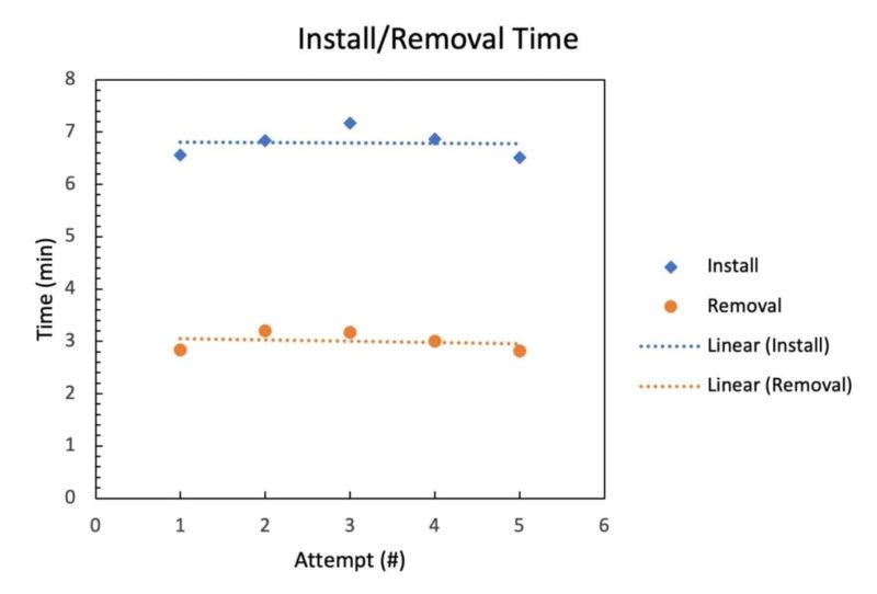
Install/Removal Time Test- The purpose of this test is to verify that the device can be installed and removed in a reasonable amount of time. The average removal time of the device is around three minutes, whereas the average installation time is closer to seven minutes, more than twice as much as installation.

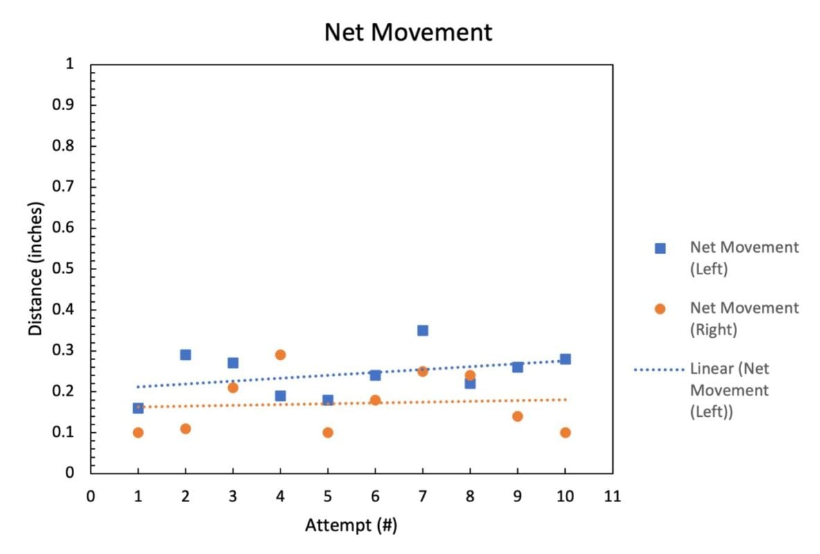
Planar Displacement Test- The purpose of this test is to verify that the device will remain immobile in the car to our specifications. All the data for the net movement in the left and right side is well below 1 in, with the highest total net movement near 0.35 inches. 


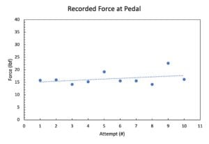
Load at Pedal Test- The purpose of this test is to ensure that the device does not require excessive force by the user to actuate the clutch pedal. The mean input force that we recorded was 16.5 lbf. We then used uncertainty analysis to validate the results of our test. We calculated the standard deviation of results to be 2.56 lbf. This is well below the threshold of 40 lbf required.

Final Design

Screen Shot 2021-06-02 at 1.28.35 PM

Here is our device completely assembled with the wire fed through the system. Obviously the clutch pedal attachment cannot be in the correct position, as there is no clutch to attach to. 

Here is our device fully installed in our sponsors vehicle. This view shows the clutch pedal attachment and wire guide assemblies.

Here is our device fully installed in our sponsors vehicle. This view shows the main structure and seat bolt attachment.

Recommendations

  • Upon analyzing the results from testing and inspection of our final design, we had recommendations on how to improve the device in the future:
  • 1. We recommend a more streamlined design in future iterations that would allow a quicker and easier installation of the device.
  • 2. We would recommend reinforcements in the horizontal pedal design to be able to take a higher load. Ways to do this:
    • -Replace the hinge with a stronger material
    • -Optimizing the spring mechanism used
    • -Reduce the friction throughout the system
    • -Optimizing the amount of wire pull versus the amount of clutch travel in the system
  • 3. Our biggest recommendation is that this device be redesigned to decrease the force required to actuate the clutch pedal. 

Our Project Slides

Our sponsors vehicle
Manufacturing using hacksaw
Concept Prototype
Angled view of Final Prototype in vehicle
Side view of Final Prototype in vehicle
Previous
Next

Have a Question About this Senior Project?

Send an email to pschuste@calpoly.edu to be connected with the project team. Please include the title of the senior project you’re inquiring about in the subject line.

Interested in Sponsoring a Mechanical Engineering Senior Project?

Visit our Sponsorship Page to learn more!

Check Out More Projects!

Visit our ME Senior Projects Page to view the latest Mechanical Engineering senior projects from the class of 2021!

Share

Share on facebook
Share on twitter
Share on linkedin